
System and method for forming a back-lighted array using an omni-directional light source

a technology of backlighting array and light source, which is applied in the field of omni-directional light emitting diodes, can solve the problems of uneven brightness of display surface, spot” not having a pleasant look, and display display not uniform luminance, etc., and achieves the effect of increasing lumen output and high lumen outpu

Active Publication Date: 2007-08-28
EPISTAR CORP
View PDF2 Cites 47 Cited by
  • Summary
  • Abstract
  • Description
  • Claims
  • Application Information

AI Technical Summary

Benefits of technology

This solution eliminates hot spots and enhances light mixing, resulting in a slimmer, brighter, and more uniformly colored display without the need for diffusing films, maintaining or increasing overall brightness while reducing device thickness.

Problems solved by technology

A common problem in using LEDs as back-lights is that the resultant LCD display does not display uniform luminance, i.e., the display surface brightness is not uniform.
These “hot spots” do not have a pleasant look.
Another common problem is that the light coming from the LED devices are poorly mixed.
This solution helps minimize, but does not eliminate the problem.
This increases the chance of light mixing before reaching the LCD at the expense of increased device thickness.

Method used


Image

  • System and method for forming a back-lighted array using an omni-directional light source
  • System and method for forming a back-lighted array using an omni-directional light source
  • System and method for forming a back-lighted array using an omni-directional light source

Examples


Embodiment Construction

[0016]Prior to beginning the detailed description it would be helpful to review prior art LED devices used for back-lighting purposes.

[0017]FIG. 7 shows device 70 having three LEDs (72R, 72G and 72B) with light coming from their respective tops and passing through liquid crystal display (LCD) 71 forming hot spots 73. These hot spots are due primarily to poor color mixing between the LEDs.

[0018]FIG. 8 shows the addition of diffusing film 82 to back-lighted device 80. Device 80 has light mixing area 83 with a depth X. Note that the larger the value for X the more the light from the three LEDs (72R, 72G and 72B) will mix. However, as X increases so does the dimensional profile of the device. This makes the device bulky and decreases the light passing through LCD 81. The decreased light caused by the increased depth, coupled with the light decrease caused by diffusing film 82, leaves room for improvement.

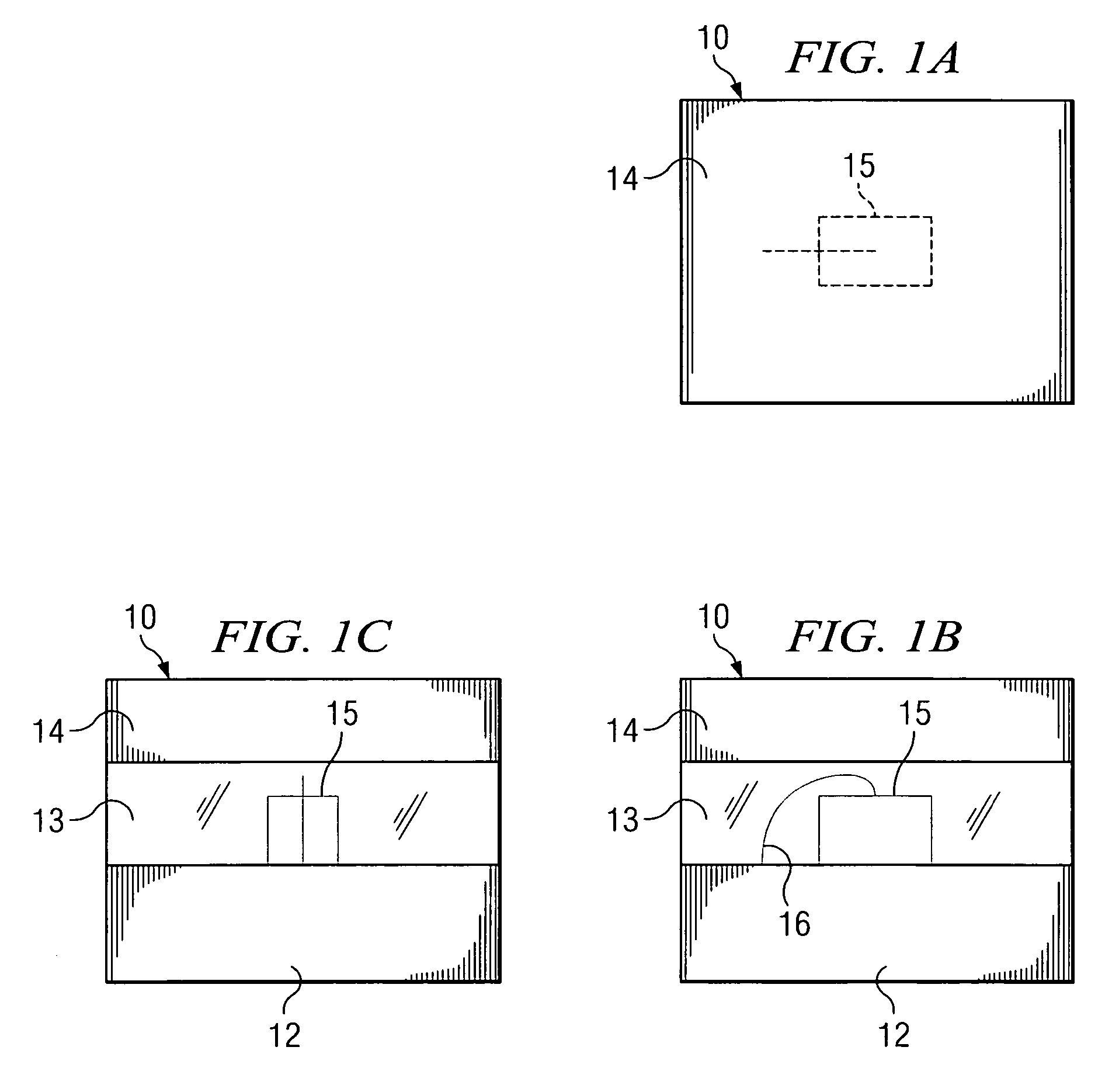
[0019]FIGS. 1A, 1B and 1C illustrate one embodiment 10 of an LED device fabricated ...


PUM


Abstract

An omni-directional LED device is constructed such that light is prevented from exiting from the top of the LED device. In one embodiment, an opaque barrier is created and in some embodiments enhancement surfaces are created below the opaque barrier to increase lumen output from the device sides. In one embodiment, a reflecting structure is created to assist with horizontal light mixing. The horizontally mixed light is then redirected through a structure, such as an LED structure, to create a high lumen output, slender back-lighted display.

Description

TECHNICAL FIELD[0001]This invention relates to light emitting devices and more particularly to omni-directional light emitting diodes (LEDs) used to form a back-lighted array.BACKGROUND OF THE INVENTION[0002]Back-lighted display devices have become popular for a variety of display purposes. Some of these displays are large and some small. The actual light for such devices is provided, as the name implies, from behind (the side away from a viewer). Light emitting diodes (LEDs) are now increasingly being used to provide the light source in such back-lighted applications.[0003]An example of an LED lighted application is a liquid crystal display (LCD) where a number of LEDs are spatially distributed behind the LCD so that their light transmits through the LCD. The light from each LED is filtered by the LCD to provide red, green and blue pixels.[0004]LED devices are directional light sources where the light is typically directed towards the central axial direction of the LED. A common pr...

Claims


Application Information

Patent Timeline
Patent Type & Authority Patents(United States)
IPC IPC(8): H01L33/00F21Y101/02
CPCG02F1/133603G02B19/0066G02B19/0071G02B19/0028G02B19/0061G02F1/133611
Inventor NG, KEE YEAN
Owner EPISTAR CORP
Learn More