
Crosstalk canceler

a cancellation device and crosstalk technology, applied in the field of audio signal processing, can solve the problem that the cancellation device is everywhere less effective than the other, and achieve the effect of allowing the listener to move freely

Inactive Publication Date: 2007-08-28
ABEL JONATHAN S
View PDF9 Cites 17 Cited by
  • Summary
  • Abstract
  • Description
  • Claims
  • Application Information

AI Technical Summary

Benefits of technology

[0015]To provide greater listener freedom of movement, the basic idea is to cancel different frequency bands at different locations, rather than to cancel all frequency bands at the same location as is currently practiced. In this way, changes in listener position do not eliminate cancellation, but shift the part of the signal canceled. In addition, this widening of the sweet spot creates a smooth transition between regions of effective cancellation and no cancellation.
[0018]The inventive canceler has an equalization which takes into account the signal arriving at the ears of a variety of listeners positioned in a range of locations. The inventive equalization is the one minimizing the timbre change over an expected range of listener positions and listener acoustic characteristics. Whereas the power spectrum of the traditional crosstalk canceler equalization has a number of peaks and valleys, that of the inventive equalization is by comparison smooth.
[0019]The timbre of output from cancelers using the inventive equalization, in fact, is less sensitive to listener position or acoustic properties than is that from the traditional canceler [1]. In addition, the inventive equalization has the unexpected benefit or reducing artifacts for listeners outside the sweet spot.
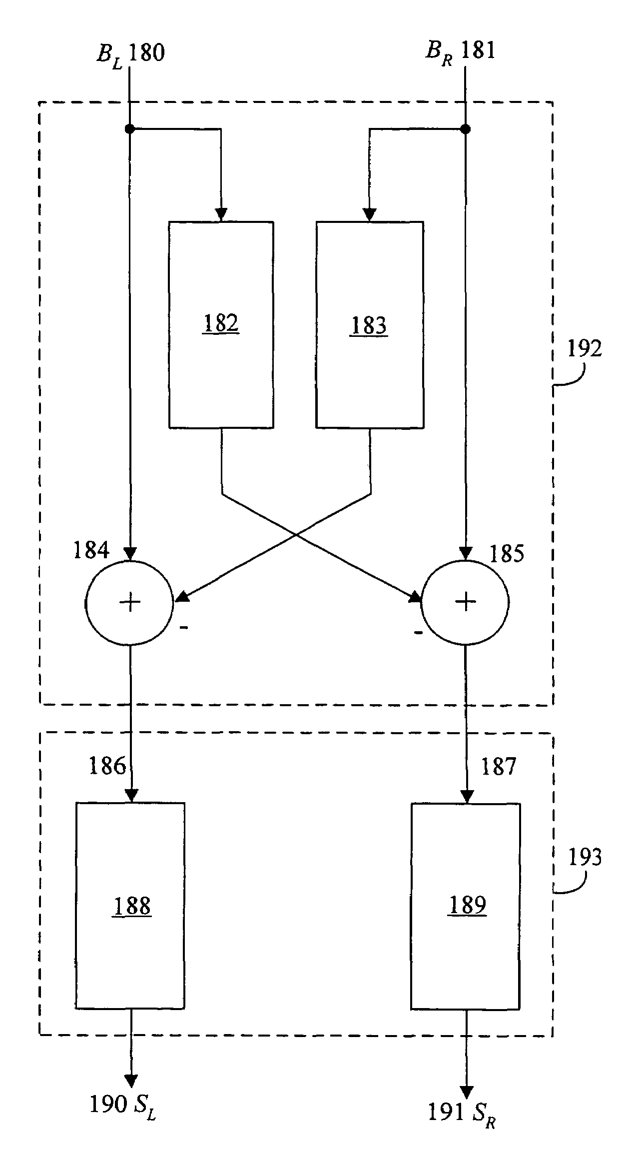
[0021]One embodiment of the invention is a crosstalk canceler providing greater listener freedom of movement comprising an input audio signal, two output channels, and a network of filters designed to eliminate crosstalk at the ear of a listener at different listener positions for different frequency bands of the input audio signal.

Problems solved by technology

The expectation in canceling different frequency bands at different locations is that while the set of listener positions where some cancellation occurs is broader, the cancellation is everywhere less effective than at the sweet spot of a traditional canceler.

Method used


Image

  • Crosstalk canceler
  • Crosstalk canceler
  • Crosstalk canceler

Examples


Embodiment Construction

[0055]For clarity, the invention will be described with respect to the symmetric two-speaker, one-listener crosstalk scenario of FIG. 4. Modifications needed to apply the invention to asymmetric crosstalk geometries, to multiple listeners, or to more than two speakers will be readily apparent to those skilled in the art. In the following, references to listener position or ear position refer also to listener orientation as well as other geometric factors including speaker position and orientation. In addition, in the following equivalent time-domain and frequency-domain quantities and operations are used interchangeably; any technique discussed or description given in one domain is meant to apply in the other. Finally, the functions “mean” and “average” are to be understood in their general sense, for instance being weighted or unweighted arithmetic, geometric, or trimmed means and the like.

Crosstalk Cancellation

[0056]To better appreciate aspects of the present invention, the tradit...


PUM


Abstract

The invention is a crosstalk canceler wherein different frequency bands are canceled at different locations so as to allow greater listener movement about the “sweet spot” while maintaining effective crosstalk cancellation. A spectrally smooth canceler equalization is used, reducing artifacts for listeners away from the sweet spot and further enlarging the sweet spot. Finally, the canceler equalization is adapted to either the anticipated or the actual crosscoherence among the input channels, producing a natural equalization regardless of the input.

Description

CROSS REFERENCE TO RELATED APPLICATION[0001]This application is a divisional application and claims the priority benefit of U.S. patent application Ser. No. 09 / 195,745, entitled “Crosstalk Canceler,” filed Nov. 18, 1998, now U.S. Pat. No. 6,668,061 which claims benefit of U.S. Provisional Application No. 60 / 065,637 filed Nov. 18, 1997 and U.S. Provisional Patent Application No. 60 / 069,015 filed Dec. 10, 1997. The foregoing applications are incorporated by reference.BACKGROUND OF THE INVENTION[0002]This invention pertains to audio signal processing, and specifically to a system and method for crosstalk cancellation.[0003]There are a number of settings in which separate audio signals are prepared for the left and right ears of a listener. Such signals are referred to as binaural signals, and are distinct from stereo signals in that the left and right binaural channels are intended to be heard only by the respective left and right ears of the listener.[0004]Binaural signals are typical...

Claims


Application Information

Patent Timeline
IPC IPC(8): H04R5/00H04S3/00
CPCH04S1/002H04S3/00H04S2400/01H04S7/307
Inventor ABEL, JONATHAN S.
Owner ABEL JONATHAN S
Learn More