Fast testing system for optical transceiver and testing method thereof

a testing system and optical transceiver technology, applied in the direction of transmission monitoring, optical radiation measurement, instruments, etc., can solve the problems of reducing production efficiency, wasting too much time, and long testing time, so as to improve production efficiency, improve competitiveness, and measure the bit error ratio

Inactive Publication Date: 2007-08-28
PHYTREX TECH CORP
View PDF3 Cites 18 Cited by
  • Summary
  • Abstract
  • Description
  • Claims
  • Application Information

AI Technical Summary

Benefits of technology

[0010]The present invention provides a testing system and method in the testing environment for the optical transceiver, which integrates multiple testing instruments, so that the user can employ the testing system for the optical transceiver to rapidly and simultaneously measure multiple products, so as to improve the production efficiency; in which, by combining an optical channel selector (OCS) with a set of digital communication analyzer and optical spectrum analyzer for switching multiple products to be tested for overall automatic testing, and with a tree coupler (TC) to synchronously transmit the measurement signals of the golden sample to multiple products to be tested in a multi-port transmission manner for further measuring the bit error ratio. Thus, the product analysis report for the user is in real-time, so as to effectively improve the competitiveness of the industry.

Problems solved by technology

In consideration of the prior art, it can only measure one product at the same time, which cannot effectively increase the quantity of testing along with the increasing of the products to be tested, and repetitive one-time measurement may make the testing time too long and waste too much time, thus the production efficiency will be reduced, and not compliant to economical cost and timely efficiency.

Method used


Image

  • Fast testing system for optical transceiver and testing method thereof
  • Fast testing system for optical transceiver and testing method thereof
  • Fast testing system for optical transceiver and testing method thereof

Examples


Embodiment Construction

[0022]Although the present invention is referenced with the appended figures for the preferred embodiment in the present invention, it should be appreciated that the skilled in the present art may modify the invention described in the specification and achieve the same effect as the present invention. Thus, it should be appreciated that the following description is construed as a broad disclosure to the skilled in the present art, and the disclosure does not limit the present invention.

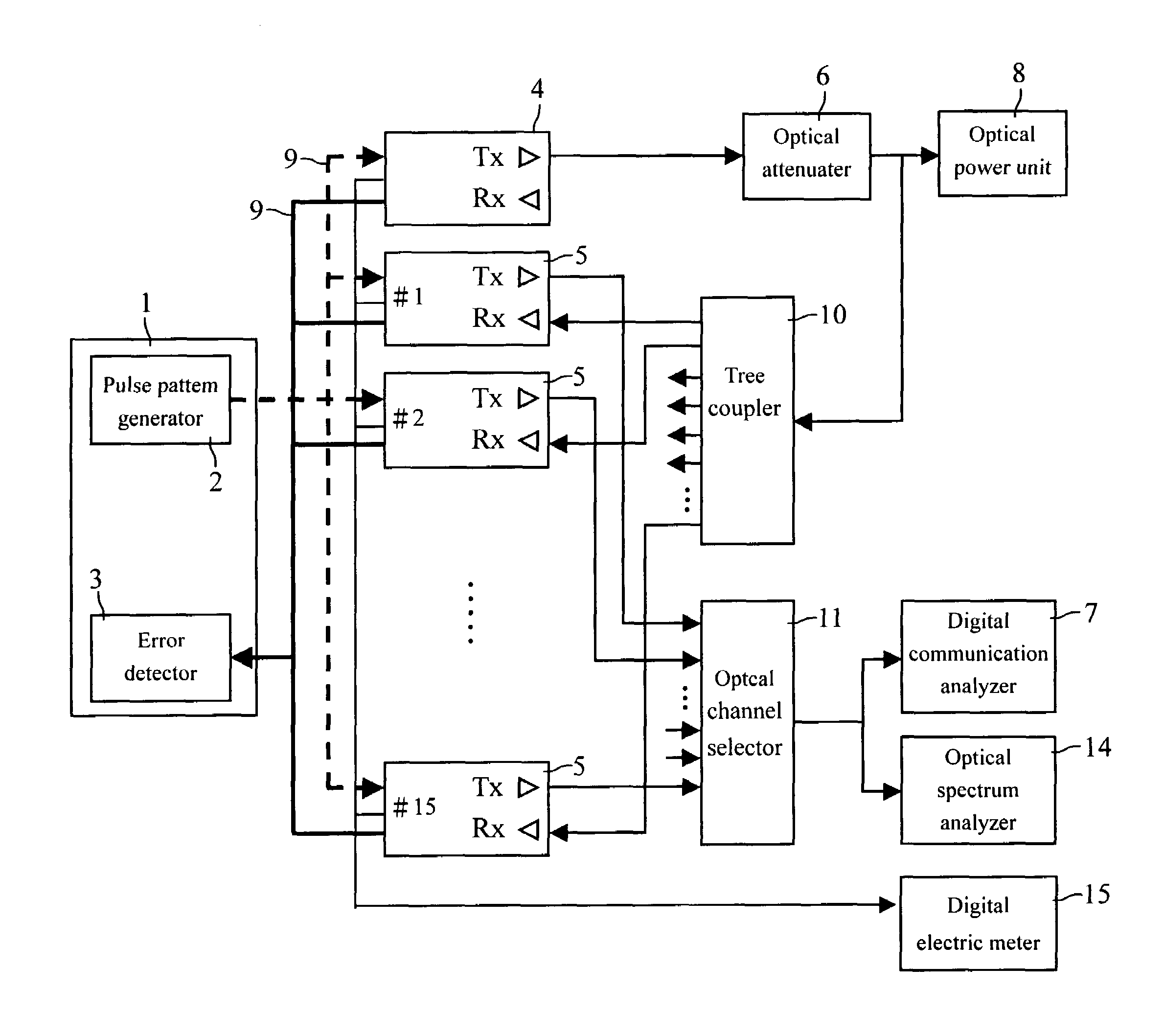
[0023]Referring to FIG. 4, it shows an implementation structure for the fast testing system of optical transceiver according to the present invention. One embodiment in the present invention uses 15 products to be tested as the testing quantity. Each product is a duplex transceiver with two optical terminals respectively for a transmitter and a receiver. As shown in FIG. 4, the fast testing system for optical transceiver according to the present invention is applied in the testing environment for opti...


PUM


Abstract

The present invention provides a fast testing system and method for optical transceiver, which integrates multiple testing machines in the testing environment for the optical transceiver, so that the user can employ the testing system for optical transceiver for rapid and simultaneous measurement of multiple products, and further improving the production efficiency. Moreover, with a combination of optical channel selector with a set of digital communication analyzer and spectrum analyzer, a plurality of products to be tested can be switched for parametric inspection, and by combining a tree coupler to synchronously transmit the measurement signals of the standard sample to the product to be tested in a multi-port transmission to further measure the bit error ratio. Thus, the product analysis report for the user is in real-time, so as to effectively improve the competitiveness of the industry.

Description

BACKGROUND OF THE INVENTION[0001]1. Technical Field[0002]The present invention relates to a fast testing system and method for optical transceiver; and, more specifically, and by integrating multiple testing instruments that, the user can employ the testing system for the optical transceiver to rapidly and simultaneously measure multiple products, so as to improve the testing efficiency.[0003]2. Description of Related Art[0004]Because the best performance evaluation method for an optical transmission device is to calculate the probability of errors happened when sending bits from a transmitter to a receiver, so called the bit error ratio (BER). Normally, a bit error ratio testing system comprises a pulse pattern generator (PPG) and an error detector (ED). Referring to FIG. 1, it shows an implementation structure for the conventional testing system for the optical transceiver. The conventional testing system for the optical transceiver comprises a digital data analyzer 1 (DDA), where...

Claims


Application Information

Patent Timeline
Patent Type & Authority Patents(United States)
IPC IPC(8): H04B10/08G01M11/00H04B3/462H04B17/00
CPCG01M11/332
Inventor PENG, JACK
Owner PHYTREX TECH CORP
Why Eureka
Try Eureka