
Endoscope

Active Publication Date: 2007-09-11
HOYA CORP +1
View PDF15 Cites 84 Cited by
  • Summary
  • Abstract
  • Description
  • Claims
  • Application Information

AI Technical Summary

Benefits of technology

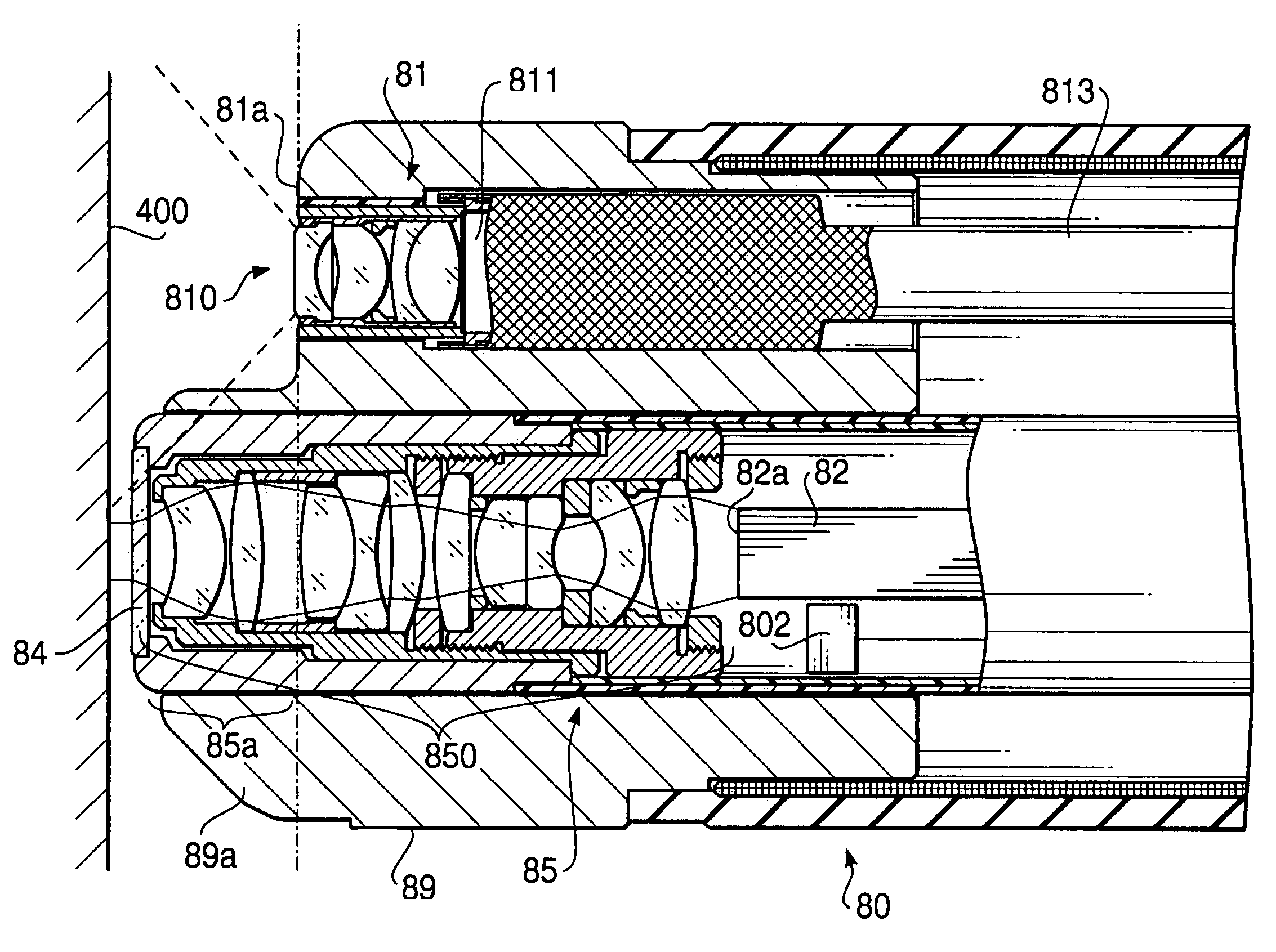
[0010]The present invention is advantageous in that an endoscope is provided, which includes two optical systems that have different magnifications, and a positional relationship between the areas observed using the two optical systems can be recognized without difficulties.
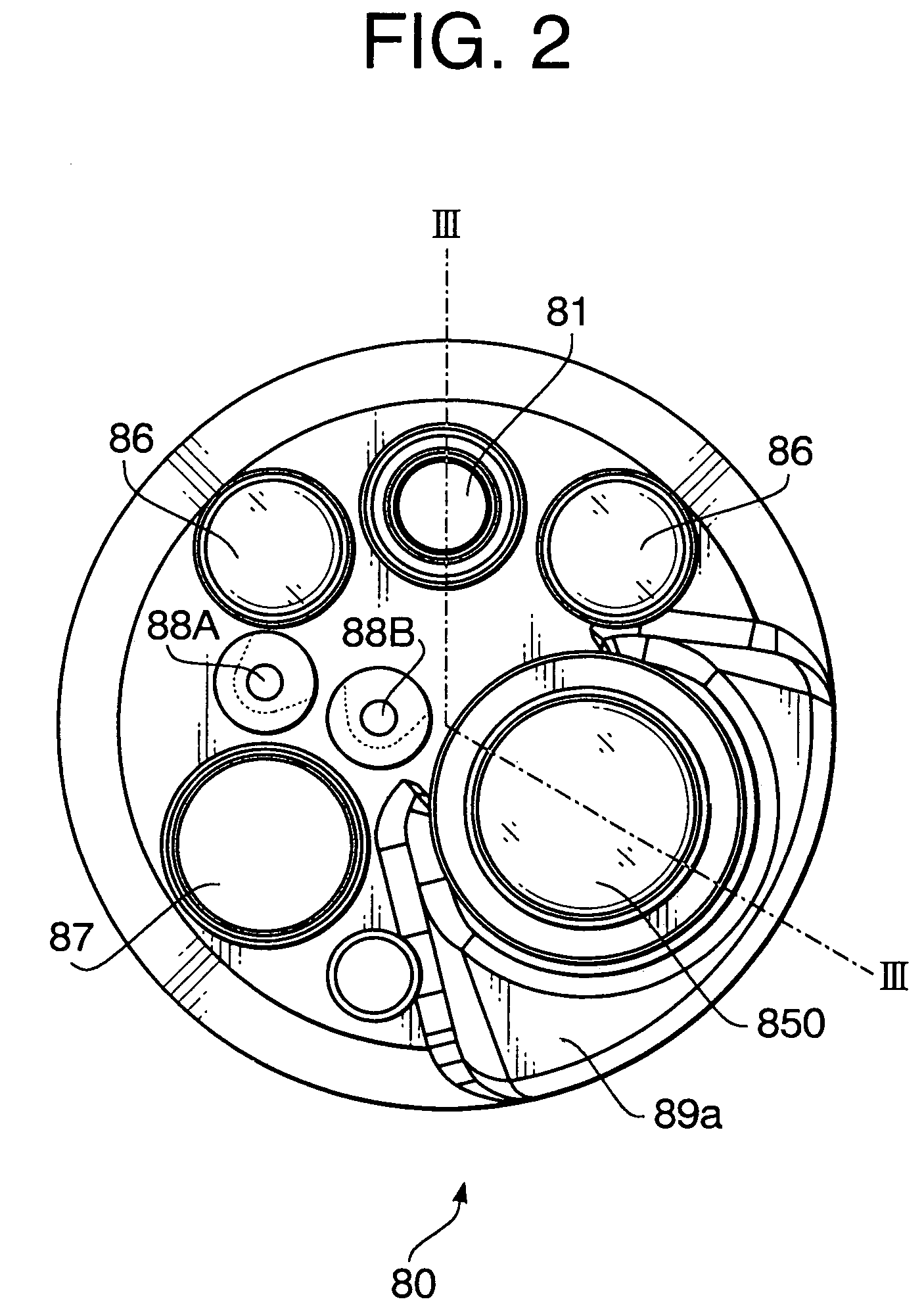
[0012]In the endoscope arranged as describe above, an operator of the endoscope can easily recognize the positional relationship between the field of views of the first optical system and the second optical system since they are integrally mounted onto the flexible inserting tube.
[0014]With such a configuration, the operator of the endoscope can locate, with ease, the second optical system in front of a target, which is firstly found in the field of view of the first optical system, with viewing the position of the second optical system in the same field of view.

Problems solved by technology

However, it is difficult for the operator to know how much the tip end of the endoscope should be moved because of the following reasons.
Therefore, it is difficult for the operator to recognize whether the confocal probe is located at an intended position merely by comparing the images obtained by the low magnification optical system and the confocal optical system.
Secondly, since the confocal probe can freely slide along the accessory channel, the relative position of the confocal probe with respect to the low magnification optical system is not fixed, and the positional relationship between the areas observed by the low magnification optical system and the confocal probe is unknown.
Due to the above reasons, it is difficult for the operator to adjust the confocal probe at the right position for observing the affected portion, and a relatively long time is required for precise inspection using the confocal probe, which puts a burden upon a patient.

Method used


Image

  • Endoscope
  • Endoscope
  • Endoscope

Examples


Embodiment Construction

[0040]Hereinafter, an embodiment of the present invention will be described with reference to the accompanying drawings.

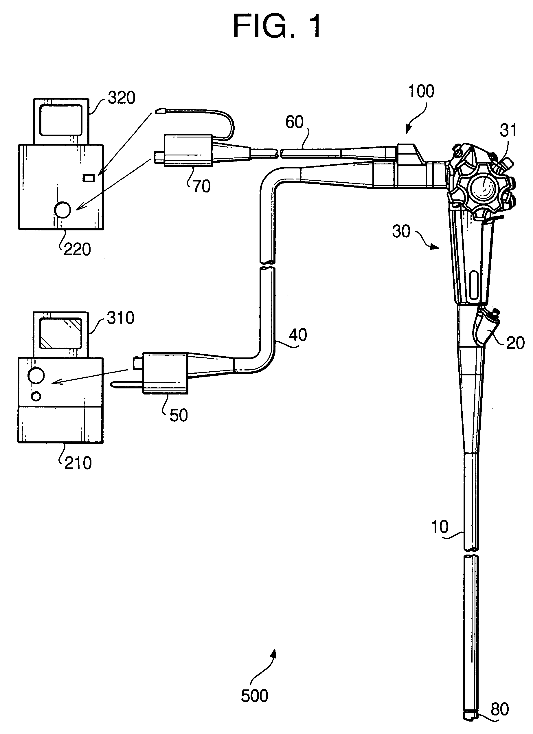
[0041]FIG. 1 schematically shows an electronic endoscope system 500 according to the embodiment of the invention. The electronic endoscope system 500 includes an electronic endoscope 100, a first processor 210, a second processor 220, a first monitor 310 and a second monitor 320. As will be describe later, the electronic endoscope 100 includes a first optical system for observing in vivo tissues inside the human body at a low magnification and a second optical system for observing the in vivo tissues at a high magnification. The first processor 210 processes and displays the low magnification image on the first monitor 310. The second processor 220 processes and displays the high magnification image on the second monitor 320.

[0042]The electronic endoscope 100 includes a flexible inserting tube 10, which is to be inserted into a human body, and an operation portion ...


PUM


Abstract

An endoscope has an inserting tube to be inserted into a human body, first and second optical systems integrally secured to a tip end portion of the inserting tube. The first and second optical systems are for observing the in vivo tissues at different magnifications. A front end portion of the second optical system is protruded by a predetermined amount with respect to a front end portion of the first optical system so that the front end portion of said second optical system is located within a field of view of said second optical system.

Description

BACKGROUND OF THE INVENTION[0001]The present invention relates to endoscopes having optical systems.[0002]An endoscope is generally provided with an observing optical system, which is used for observing in vivo tissues inside a human cavity. In particular, in an electronic endoscope, an objective optical system is provided as the observing optical system, and an image of a target portion (e.g., tissues in the human cavity) is formed on a solid state image capturing element such as a CCD (Charge Coupled Device).[0003]Recently, a confocal probe, which employs principle of confocal micrography, has become widely known. The confocal probe is configured to illuminate in vivo tissues inside human cavity, and selectively receive light reflected by the tissues on an object side focal plane. The confocal probe is provided with a specific optical system (i.e., a confocal optical system) which has a relatively high magnification.[0004]The confocal probe is typically inserted in an accessory ch...

Claims


Application Information

Patent Timeline
IPC IPC(8): A61B1/06A61B1/05
CPCA61B1/00096A61B1/00181A61B1/05
Inventor OKADA, SHINSUKEDELANEY, PETER MAXWELL
Owner HOYA CORP
Learn More