Optical automatic protection switching mechanism for optical channel shared protection rings

a technology of automatic protection and protection switching, applied in the field of optical communication networks, can solve the problems of service layer protection intractable, protocol and algorithm protection not designed, and the best possible approach

Inactive Publication Date: 2007-09-11
MICROSOFT TECH LICENSING LLC +1
View PDF5 Cites 27 Cited by
  • Summary
  • Abstract
  • Description
  • Claims
  • Application Information

AI Technical Summary

Problems solved by technology

In fact, a major network failure, such a fiber cut or node failure, would impact an extremely large number of client layer devices (e.g., ATM switches or IP routers), making service layer protection intractable.
In this approach the required protocols and algorithms for protection are not designed for the specific case of a ring topology.
Although it is true that such

Method used


Image

  • Optical automatic protection switching mechanism for optical channel shared protection rings
  • Optical automatic protection switching mechanism for optical channel shared protection rings
  • Optical automatic protection switching mechanism for optical channel shared protection rings

Examples


case 1

[0037] Bi-Directional Failure

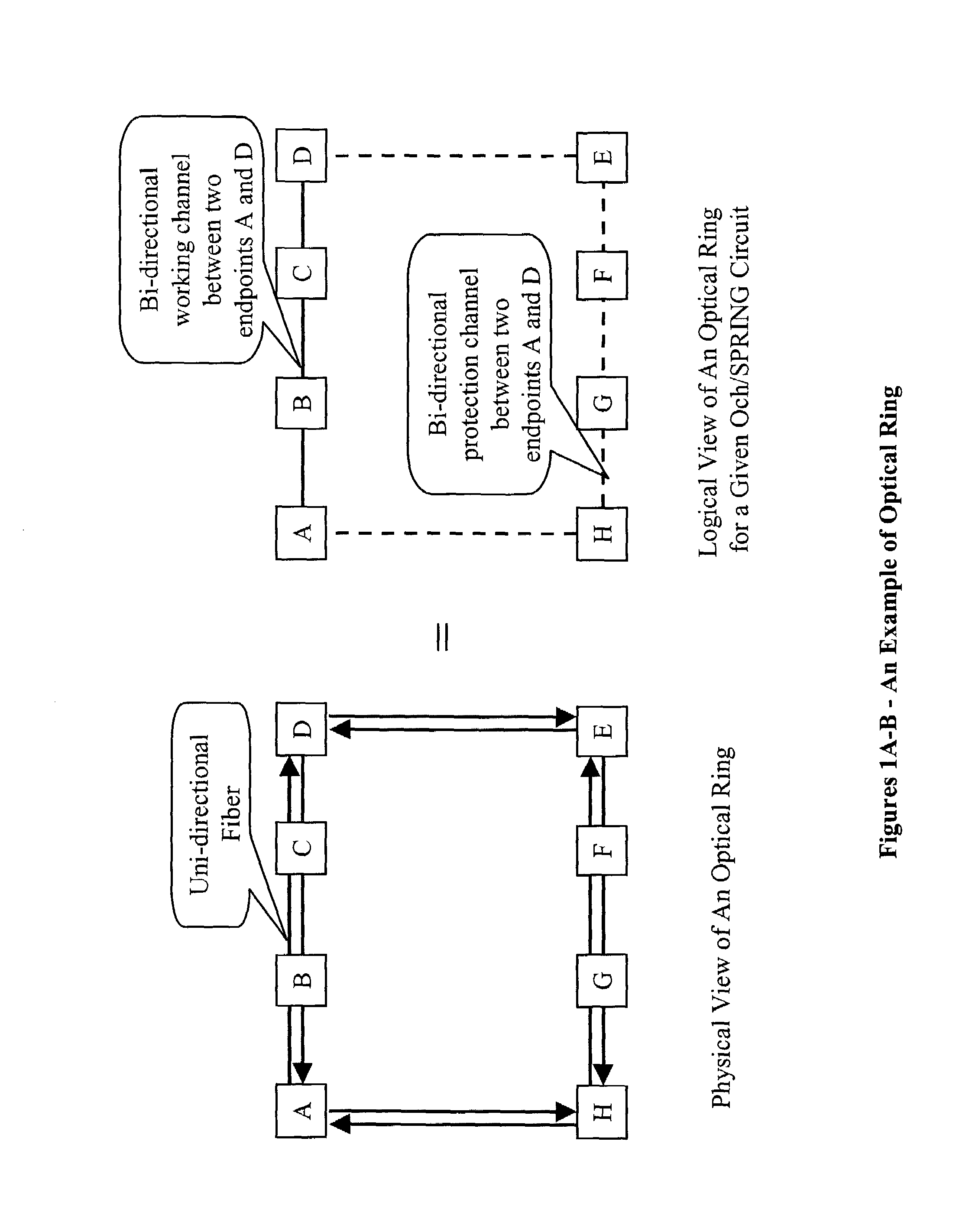
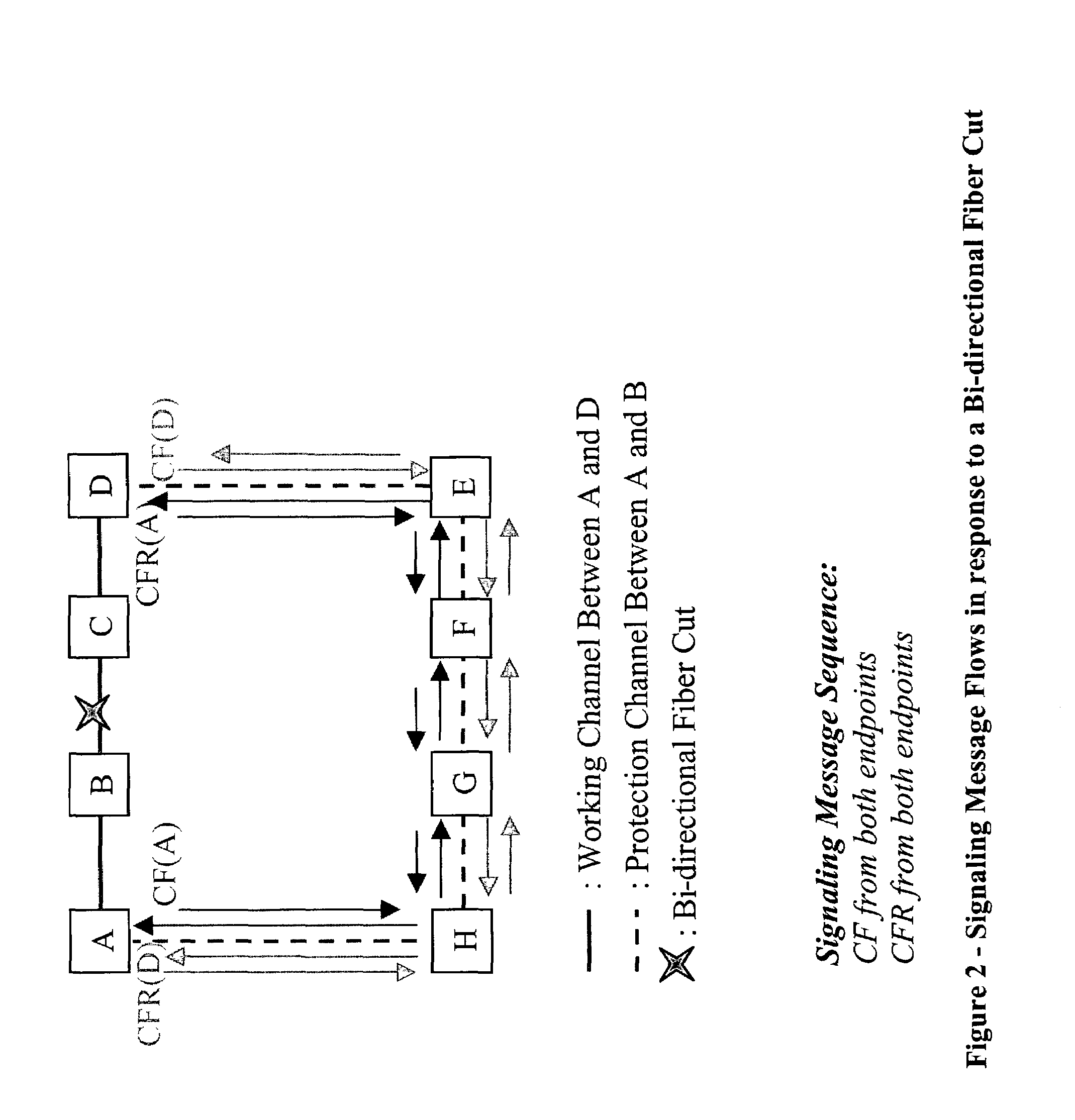
[0038]First, we discuss the messaging flow in response to bi-directional failure, such as a bi-directional fiber cut. Assume that after a bi-directional fiber cut between nodes B and C, both endpoints A and D detect a failure via a lower layer mechanism that is vendor specific. Upon detecting the failure, both endpoint nodes (A and D) initiate protection switching by generating channel failure (CF) messages toward each other along the protection path (e.g., the long path). Thus, protection switching is initiated from both ends simultaneously, or nearly so depending upon the relative notifications of the failure by the lower layer mechanisms.

[0039]All nodes on the protection path including both end nodes and intermediate nodes will perform following tasks. Upon receiving the first channel failure message, regardless of where it is originated, each node initiates protection switching actions for both directions and forwards the channel failure message to t...

exemplary embodiment 90

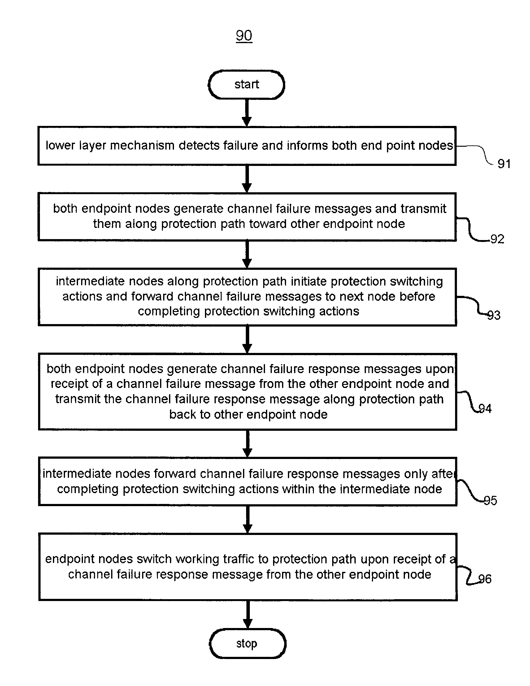
[0047]FIG. 9 depicts an exemplary embodiment 90 of a method for performing protection switching in flow chart summary form. In step 91, a lower layer mechanism detects failure and informs both endpoint nodes. The detection mechanism can vary according to vendor equipment.

[0048]Next, both endpoint nodes generate channel failure messages and transmit them along protection path toward other endpoint node (step 92). These failure mechanisms may be transmitted at slightly different times, depending upon the mechanism that detects the failure and its relationship to the endpoint nodes, as well as the processing variations in the two endpoint nodes. Nevertheless, these two endpoint nodes will initiate protection switching as quickly as possible from both ends of the protected link.

[0049]Intermediate nodes along the protection path initiate protection switching actions and forward all received channel failure messages to the next node in line along the protection path before completing prot...

case 2

[0053] Uni-Directional Failure

[0054]For a uni-directional fiber cut, only the end node on the receiving side of the uni-directional failure can detect the failure. After detecting a failure, the end node on the receiving side of the uni-directional failure will initiate the protection switching action by generating a channel failure message towards the source along the protection path (e.g., the longer path) and immediately notify the other end node via working channel, e.g., the short path, by sending, e.g., a SONET K-byte short path signal toward the other end.

[0055]The time to take for the other end node to be notified will be the time of composing the K-byte signaling, plus the propagation delay of speed of light and the processing delay at the receiving end. As soon as the other end node receives the K-byte signal, the other end node sends out the channel failure message along the protection path. It is very unlikely that an end node X receives a channel failure message from th...


PUM


Abstract

A method for performing protection switching in an optical network does so in an optimal manner by performing the protection switching actions in the various nodes of a protection path in parallel rather than in sequence. To do so, a channel failure message is transmitted from an end node A in the optical network upon detecting a failure in a link in the optical network that includes the end node A. If a failure can be detected at both end nodes, the channel failure messages are transmitted from both end nodes the moment they detect failure without any further waiting. Upon receiving the first channel failure message regardless its originating end node, switching actions in intermediate nodes are initiated. The channel failure messages are forwarded from the intermediate nodes to their corresponding next nodes before completing switching actions in the intermediate nodes. When receiving channel failure response messages, these messages are forwarded to a next node from the intermediate node only after switching actions are complete in the intermediate node. A technique for merging messages in nodes is also disclosed.

Description

RELATED APPLICATIONS[0001]This application claims the benefit of U.S. Provisional Application No. 60 / 306,710 filed on Jul. 20, 2001 by the same inventors. This application is also related to U.S. patent application Ser. No. 10 / 200,066, which is filed concurrently herewith and is hereby incorporated by reference as if repeated herein in its entirety, including the drawings.FIELD OF THE INVENTION[0002]The present invention relates generally to optical communications networks, and more particularly to an optical communication network including optical channel shared protection rings.BACKGROUND[0003]Current and next generation optical networks are capable of transporting multiple wavelengths on the same fiber by using Dense Wavelength Division Multiplexing (DWDM) technology. Typical systems are capable of transporting thirty-two or more wavelength channels, at ten Gigabits per second (Gb / s) rate each. With capacities exceeding 320 Gb / s per fiber, it is becoming increasingly efficient an...

Claims


Application Information

Patent Timeline
IPC IPC(8): H04B10/00
CPCH04J14/0283H04J14/0295H04J14/0249H04J14/0245H04J14/0227
Inventor IYER, RAVICHANDRANSAMPANGI, MANJUNATHRODRIGUEZ-MORAL, ANTONIOBONENFANT, PAULMANG, XIAOWENZHANG, LEAH
Owner MICROSOFT TECH LICENSING LLC
Why Eureka
Try Eureka