Transfer unit mounting device and image forming apparatus having the same

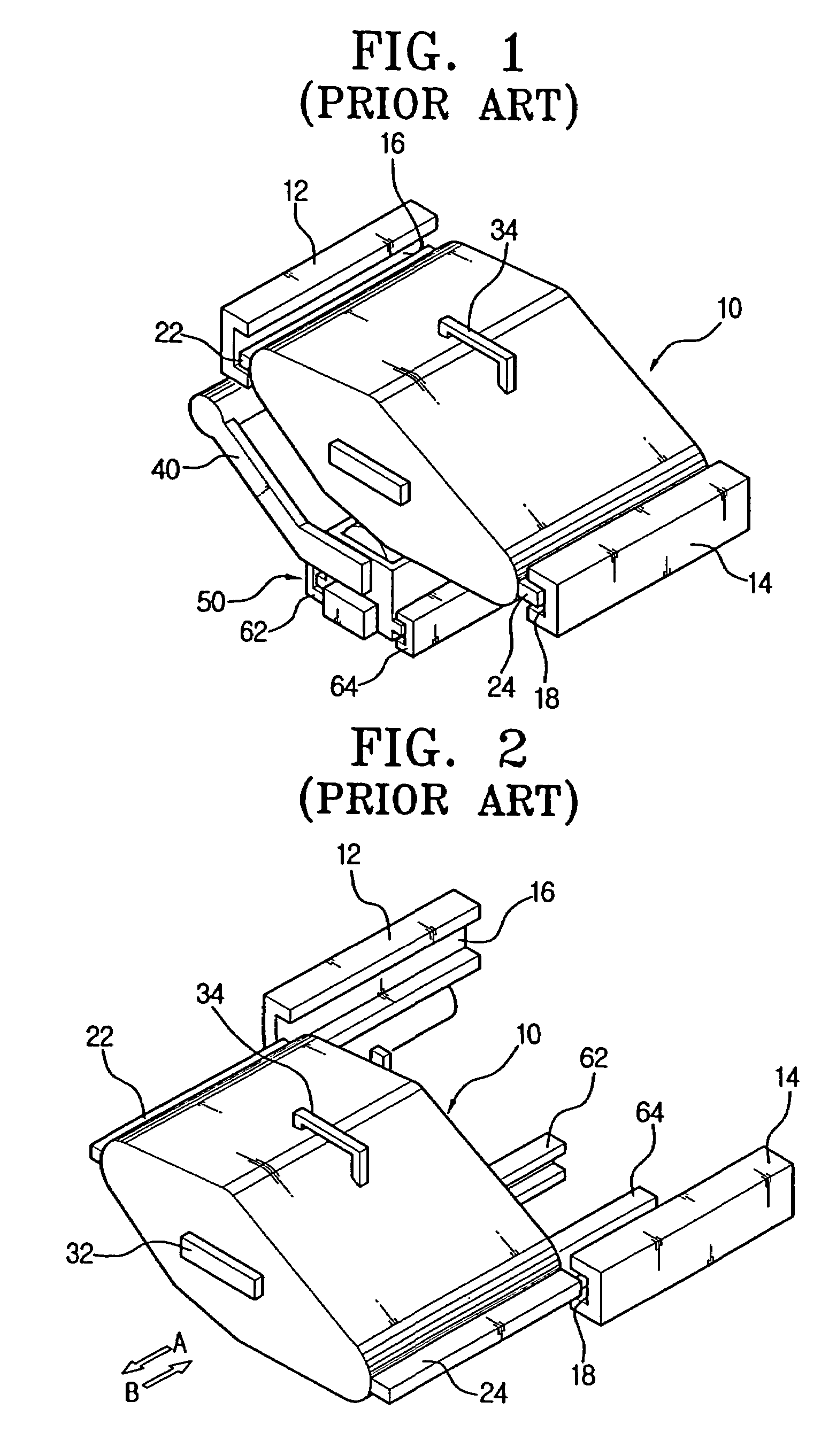
a technology of image forming apparatus and mounting device, which is applied in the direction of shock absorbers, instruments, wound springs, etc., can solve the problems of deteriorating image quality, no fixing means to securely fix, and the transfer unit b>10/b> is easily trembled or deviated, and achieves constant gap

Inactive Publication Date: 2007-09-11
S PRINTING SOLUTION CO LTD
View PDF19 Cites 9 Cited by
  • Summary
  • Abstract
  • Description
  • Claims
  • Application Information

AI Technical Summary

Benefits of technology

[0019]In order to solve the above and / or other problems it is an aspect of the present general inventive concept to provide a transfer unit mounting device of an image forming apparatus with which a user can mount and dismount a transfer unit in and from the image forming apparatus with ease, and which is capable of maintaining a substantially constant gap between the transfer unit and a developing unit.
[0020]It is another aspect of the present general inventive concept to provide a transfer unit mounting device of an image forming apparatus which is capable of mitigating an impact exerted on the transfer unit and caused by collision of the transfer unit with a developing unit or a weight of the transfer unit.
[0022]The above and / or other aspects of the present general inventive concept are achieved by providing a transfer unit mounting device of an image forming apparatus, in which a transfer unit is mounted in and dismounted from the image forming apparatus. The transfer unit may include a transfer belt driven by a plurality of rollers, and a housing to protect the transfer belt. The transfer unit mounting device may include at least one damping unit to elastically support the transfer unit to prevent a shock from being transferred to the transfer unit when the transfer unit is mounted.
[0031]The above and / or other aspects of the present general inventive concept, are also achieved by providing an image forming apparatus that may include a paper feeding device to convey paper, a photoconductive unit where an image is formed through a light scanning procedure and a developing procedure, a transfer unit to transfer the image formed on the developing unit to a printing medium, a fusing unit to affix a toner onto the printing medium, and a transfer unit mounting device having at least one damping unit to mitigate a shock to the transfer unit.

Problems solved by technology

The developing unit and the transfer unit are periodically replaced with new ones because image quality deteriorates as a predetermined time passes.
Additionally, there was no fixing means to securely fix the transfer unit 10 after the transfer unit 10 is mounted, the transfer unit 10 is easily trembled or deviated even by weak vibration.
Yet another problem is that the first and the second guide protrusions 22 and 24 collide with the first and the second guide rails 12 and 14 of the body frame when the transfer unit 10 is mounted, and the shock from the collision is directly transferred to the transfer unit 10, causing the disorder (breakdown) of the transfer unit 10 or shortening a lifespan of the transfer unit 10.
As a result, a gap between the transfer unit and the developing unit is often changed, causing a severe defect of a printing quality.

Method used


Image

  • Transfer unit mounting device and image forming apparatus having the same
  • Transfer unit mounting device and image forming apparatus having the same
  • Transfer unit mounting device and image forming apparatus having the same

Examples


Embodiment Construction

[0046]Reference will now be made in detail to the embodiments of the present general inventive concept, examples of which are illustrated in the accompanying drawings, wherein like reference numerals refer to the like elements throughout. The embodiments are described below in order to explain the present general inventive concept by referring to the figures.

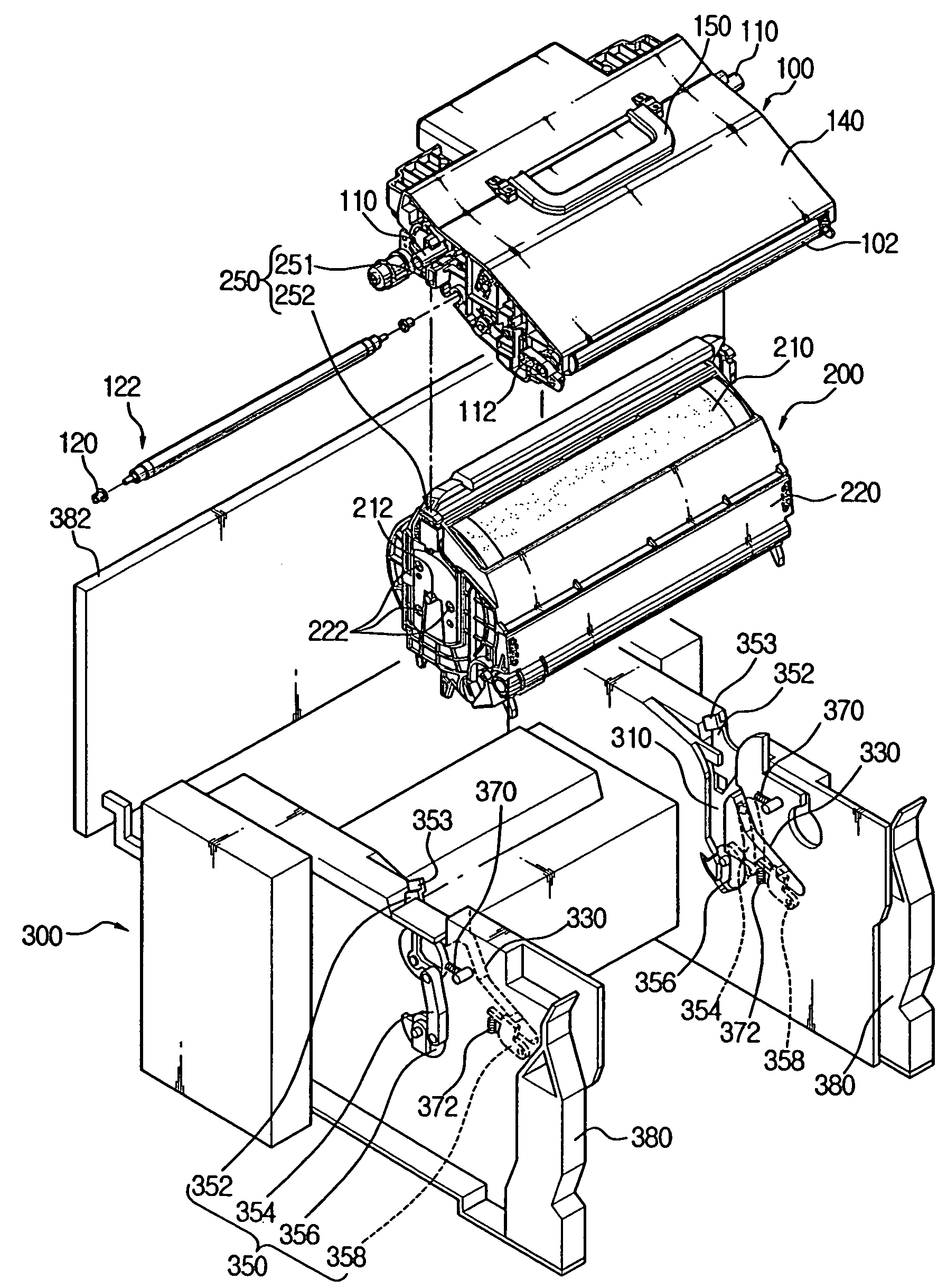
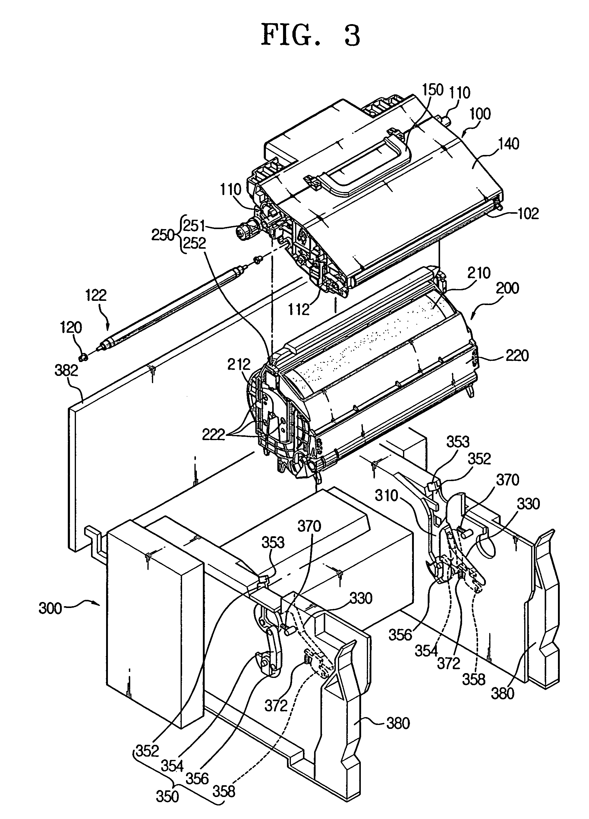
[0047]FIG. 3 is a perspective view of a transfer unit mounting device according to an embodiment of the present general inventive concept. Referring to FIG. 3, the transfer unit mounting device may include a transfer unit 100, a developing unit 200 and a body 300, FIG. 4 is an enlarged view showing a damper assembly 252 of the transfer unit mounting device of FIG. 3, and FIG. 5 is a partial cross-sectional view showing the body 300 of the image forming apparatus and the transfer unit 100 as shown in FIG. 3. The developing unit 200 may be referred to a photoconductive unit having a photoconductive (photosensitive) drum on which a...


PUM


Abstract

A transfer unit mounting device of an image forming apparatus to mount and dismount a transfer unit in and from the image forming apparatus. The transfer unit includes a transfer belt driven by a plurality of rollers, and a housing to protect the transfer belt. The transfer unit mounting device includes at least one damping unit to elastically support the transfer unit to prevent a shock from being transferred to the transfer unit when the transfer unit is mounted.

Description

CROSS-REFERENCE TO RELATED APPLICATIONS[0001]This application claims the benefit of Korean Patent Application No. 2003-72424, filed on Oct. 17, 2003, in the Korean Intellectual Property Office, the disclosure of which is incorporated herein by reference.BACKGROUND OF THE INVENTION[0002]1. Field of the Invention[0003]The present general inventive concept relates to a transfer unit mounting device to removably mount a transfer unit in an image forming apparatus, and more particularly, to a transfer unit mounting device which enables easy mounting of a transfer unit in a printer body and is capable of mitigating an impact on the transfer unit during mounting, and an image forming apparatus having the same.[0004]2. Description of the Related Art[0005]Generally, an image forming apparatus, such as a printer or a photocopier, includes a developing unit to form an image to be printed, and a transfer unit to transfer the image formed on the developing unit onto a printing medium such as pap...

Claims


Application Information

Patent Timeline
Patent Type & Authority Patents(United States)
IPC IPC(8): G03G21/16G03G15/00F16F1/06F16F7/00F16F15/06G03G15/14G03G15/16
CPCG03G15/16G03G15/1605G03G21/1628G03G21/1647G03G2221/1642G03G15/14
Inventor BAEK, CHUNG-GUKYOO, YONG-BACK
Owner S PRINTING SOLUTION CO LTD
Why Eureka
Try Eureka