Heat and mass exchanger

a mass exchanger and heat exchange technology, applied in the field of thermodynamic devices, can solve the problems of few systems being able to effectively regulate air humidity, two factors can be in conflict, and the humidity can soar to levels that are uncomfortable or even unhealthy, and achieve the effect of enhancing the exchange of thermal energy and efficient exchang

Active Publication Date: 2007-09-18
AIL RES
View PDF21 Cites 109 Cited by
  • Summary
  • Abstract
  • Description
  • Claims
  • Application Information

AI Technical Summary

Benefits of technology

[0024]The present invention is directed to a heat and mass exchanger designed to exchange a gas with a liquid, while independently maintaining the temperature of the liquid so as to maintain an efficient exchange. By way of example, the heat and mass exchanger of the present invention utilizes a liquid desiccant that is capable of altering the water vapor content of a process air stream in an efficient manner. The heat and mass exchanger includes a substrate having a surface capable of supporting the flow of the liquid thereon in contact with a gas, the surface further functioning to enhance the exchange of thermal energy between the liquid and a heat exchange fluid (gas or liquid or the same undergoing a phase change) that flows within the heat and mass exchanger.

Problems solved by technology

However, these two factors can be in conflict in certain situations.
For example, when ventilation rates are increased to improve indoor air quality, humidity can soar to levels that are uncomfortable or even unhealthy.
However, few systems are able to effectively regulate air humidity.
Conventional HVAC equipment under such conditions is limited in its ability to restore comfortable air quality.
However, this process is generally inefficient.
Unfortunately, the use of glycol as a desiccant was impractical.
In both the evaporator and the condenser, glycol will evaporate into the air streams, thus undesirably requiring periodic recharging of the system.
The LDVCACs of Drykor and AGC therefore introduce additional temperature drops that degrade the efficiency of the air conditioners.
The LDVCAC of Howell and Peterson, however, cannot be easily used with aqueous solutions of either lithium chloride or lithium bromide because these solutions are very corrosive to the metals that are commonly used to make evaporators and condensers.
While the evaporator and condenser can be made from an expensive alloy that resists corrosion, the resulting air conditioner would be too expensive to sell in the broad HVAC market.
However, these approaches of protecting the evaporator and condenser from corrosion have important limitations: plastics have a low surface energy and so are not easily wetted by liquids; and ceramics are very difficult to apply in the thin pin-hole-free coatings needed in this application.
While it is possible to add a droplet filter or demister at the air exits from both the dehumidifying and regenerating sections of the LDVCAC so that droplets do not escape from the system, this approach will create large maintenance requirements associated with keeping the filters unblocked by liquid, and increase the pressure drop that must be overcome by the system's fans.
However, the Howell-Peterson LDVCAC does not readily achieve uniform distribution of the desiccant on the surfaces of the evaporator and condenser.
However, these coatings do not enhance and may deter the spreading of the desiccant over the external surfaces of the heat exchangers.
Furthermore, Lowenstein's low-flow approach to suppressing droplets would be difficult to implement with plain plastic surfaces.
Howell and Peterson's suggestion that corrosion-resistant metallic tubes be used with plastic fins is also disadvantageous because of the poor thermal conductivity of plastics.
Although a plastic fin can be used to provide contact between the liquid desiccant and the air that flows over the fin, the fin will not effectively heat or cool the desiccant.
We have observed that the most common configuration for finned-tube HVAC heat exchangers (e.g. FIG. 3 of U.S. Pat. No. 4,984,434), in which the tubes pass through holes in the fins, will not effectively heat or cool the desiccant if the fins are plastic, even if the surface of the fins are treated so that uniform films of desiccant are created.
This is because the plastic fins are poor thermal conductors and they provide a path for the desiccant to bypass the tube i.e., the liquid desiccant can flow on a fin from the top of the evaporator / condenser to the bottom without ever coming in thermal contact with a metallic tube.

Method used


Image

  • Heat and mass exchanger
  • Heat and mass exchanger
  • Heat and mass exchanger

Examples


example

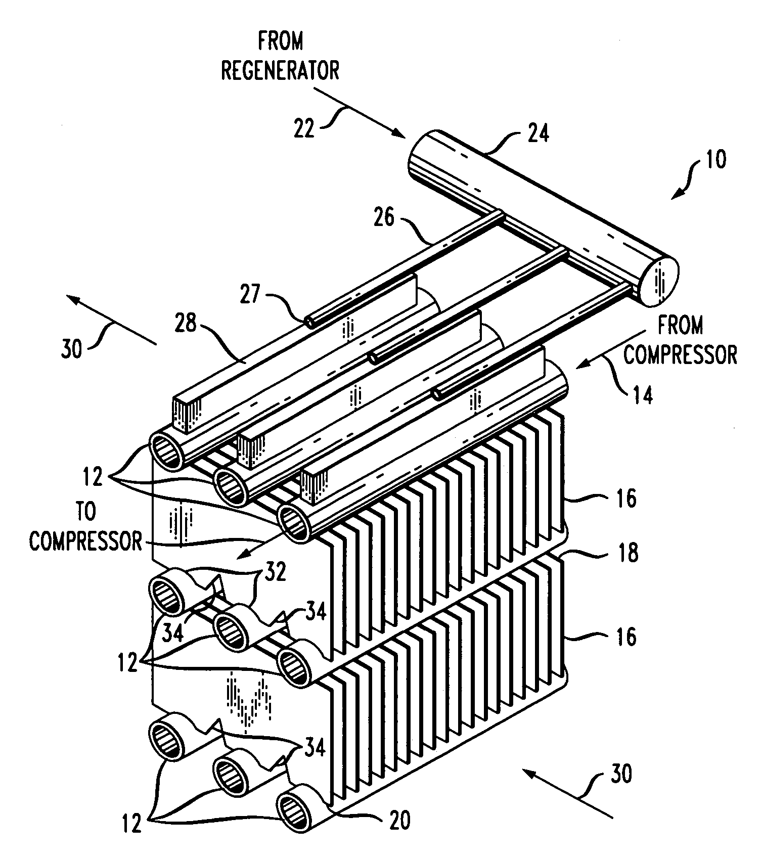
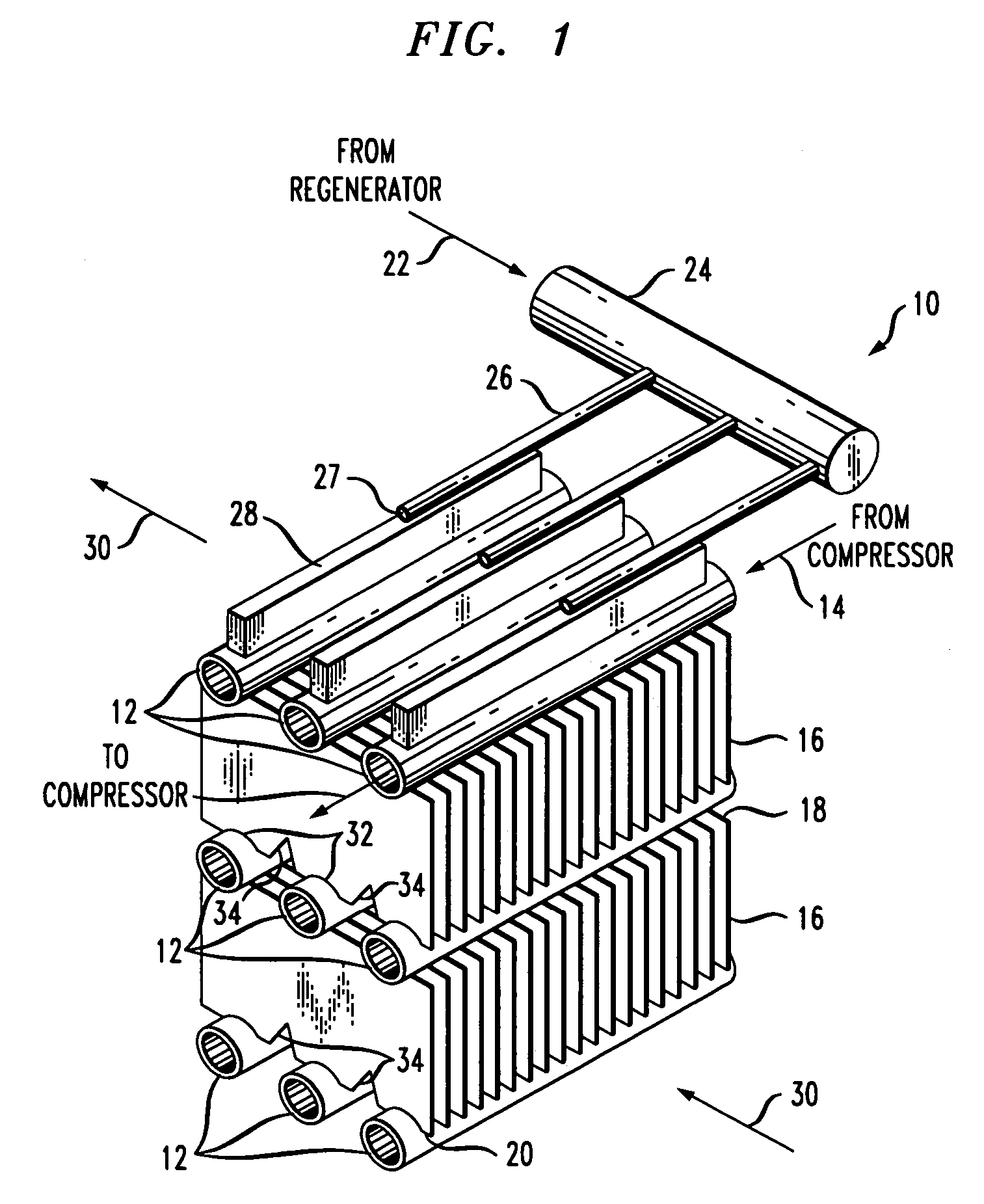
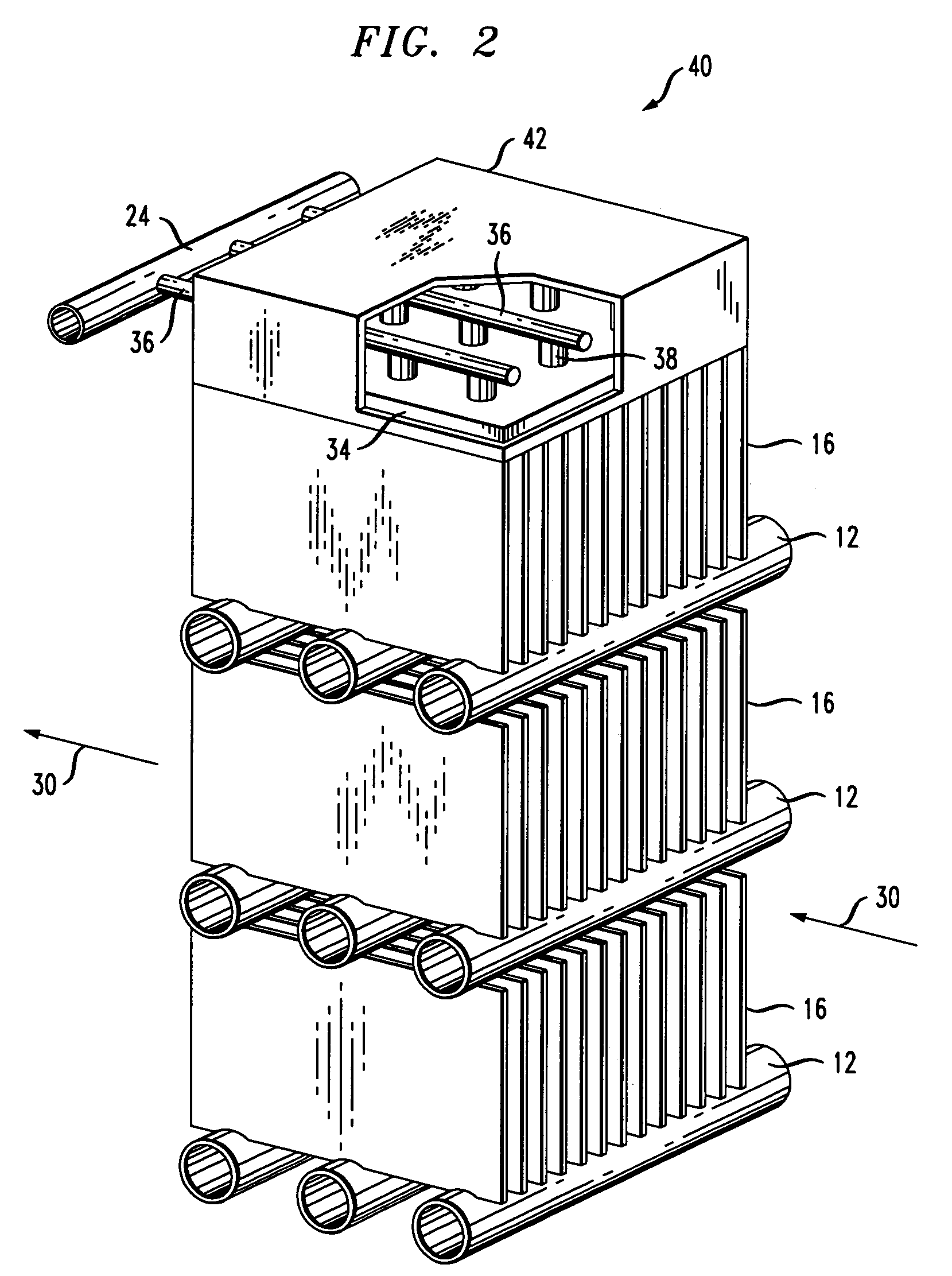
[0108]In this example, a mass and heat exchanger that is designed according to the principles taught herein is installed in a vapor-compression air conditioner to replace a conventional evaporator. The replaced conventional evaporator is an industry-standard finned-tube heat exchanger with copper tubes and aluminum fins. The conventional evaporator possesses the following characteristics:

[0109]

Total number of tubes92Number of tubes in vertical column23Number of tube columns4Tube outer diameter0.3325inFin orientationvertical and perpendicularto tubesFin height24.0inFin width2.5inFin thickness0.010inFin spacing13fins per inchVolume of air processed1000cfmFace velocity for incoming air263fpm

[0110]With R-22 refrigerant evaporating at a saturation temperature of 49° F. within the tubes of this heat exchanger and 1000 CFM of air entering at 80° F. dry-bulb temperature and 67° F. wet-bulb temperature flowing over the outside of the fins and tubes, the conventional heat exchanger absorbs 30...


PUM


Abstract

A mass and heat exchanger includes at least one first substrate with a surface for supporting a continuous flow of a liquid thereon that either absorbs, desorbs, evaporates or condenses one or more gaseous species from or to a surrounding gas; and at least one second substrate operatively associated with the first substrate. The second substrate includes a surface for supporting the continuous flow of the liquid thereon and is adapted to carry a heat exchange fluid therethrough, wherein heat transfer occurs between the liquid and the heat exchange fluid.

Description

RELATED APPLICATIONS[0001]This is a continuation application of U.S. patent application Ser. No. 11 / 103,136 filed Apr. 11, 2005, now abandoned, which claims priority to U.S. Provisional Patent Application Ser. No. 60 / 561,182 filed Apr. 9, 2004.GOVERNMENT INTEREST[0002]The invention described and claimed herein may be manufactured, used and licensed by or for the United States Government.[0003]This invention is made with Government support under SBIR Grant No. DE-FG02-03ER83600 awarded by the Department of Energy. The Government has certain rights in this invention.FIELD OF THE INVENTION[0004]The present invention relates to thermodynamic devices, and more particularly to a heat and mass exchanger.BACKGROUND OF THE INVENTION[0005]Proper ventilation and regulation of humidity are essential for maintaining healthy and comfortable air quality indoors. However, these two factors can be in conflict in certain situations. For example, when ventilation rates are increased to improve indoor ...

Claims


Application Information

Patent Timeline
Patent Type & Authority Patents(United States)
IPC IPC(8): F25D23/00F28D5/00F24F3/14F28D3/02F28F1/32
CPCF24F3/1417F28D1/05333F28D1/05383F28D21/0015F28F1/32F28F13/187F28D3/02F28F2240/00
Inventor LOWENSTEIN, ANDREWSIBILIA, MARC J.MILLER, JEFFREY A.TONON, THOMAS
Owner AIL RES
Why Eureka
Try Eureka