Electrophotographic image forming apparatus

a technology of forming apparatus and forming chamber, which is applied in the direction of electrographic process apparatus, corona discharge, instruments, etc., can solve the problems of user erroneous demounting of drum cartridges, and achieve the effect of suppressing erroneous demounting of cartridges, improving cartridge exchange operation, and convenient cartridge exchang

Active Publication Date: 2012-10-16
CANON KK
View PDF12 Cites 16 Cited by
  • Summary
  • Abstract
  • Description
  • Claims
  • Application Information

AI Technical Summary

Benefits of technology

[0005]A principal object of the present invention is to provide an electrophotographic image forming apparatus which has enabled individual exchange of consumables such as a photosensitive member and a developer and has realized improvement in cartridge exchange operativity.
[0017]According to the present invention, it is also possible to provide an electrophotographic image forming apparatus improved in mounting and demounting operativity of the cartridge with respect to the cartridge supporting member by the user.

Problems solved by technology

For this reason, there was a possibility that the user erroneously demounted the drum cartridge from the holder member earlier than the developing cartridge even in the case where only the developing cartridge was required to be exchanged due to consumption of the developer.

Method used


Image

  • Electrophotographic image forming apparatus
  • Electrophotographic image forming apparatus
  • Electrophotographic image forming apparatus

Examples


embodiment 1

[Embodiment 1]

(General Structure of Electrophotographic Image Forming Apparatus)

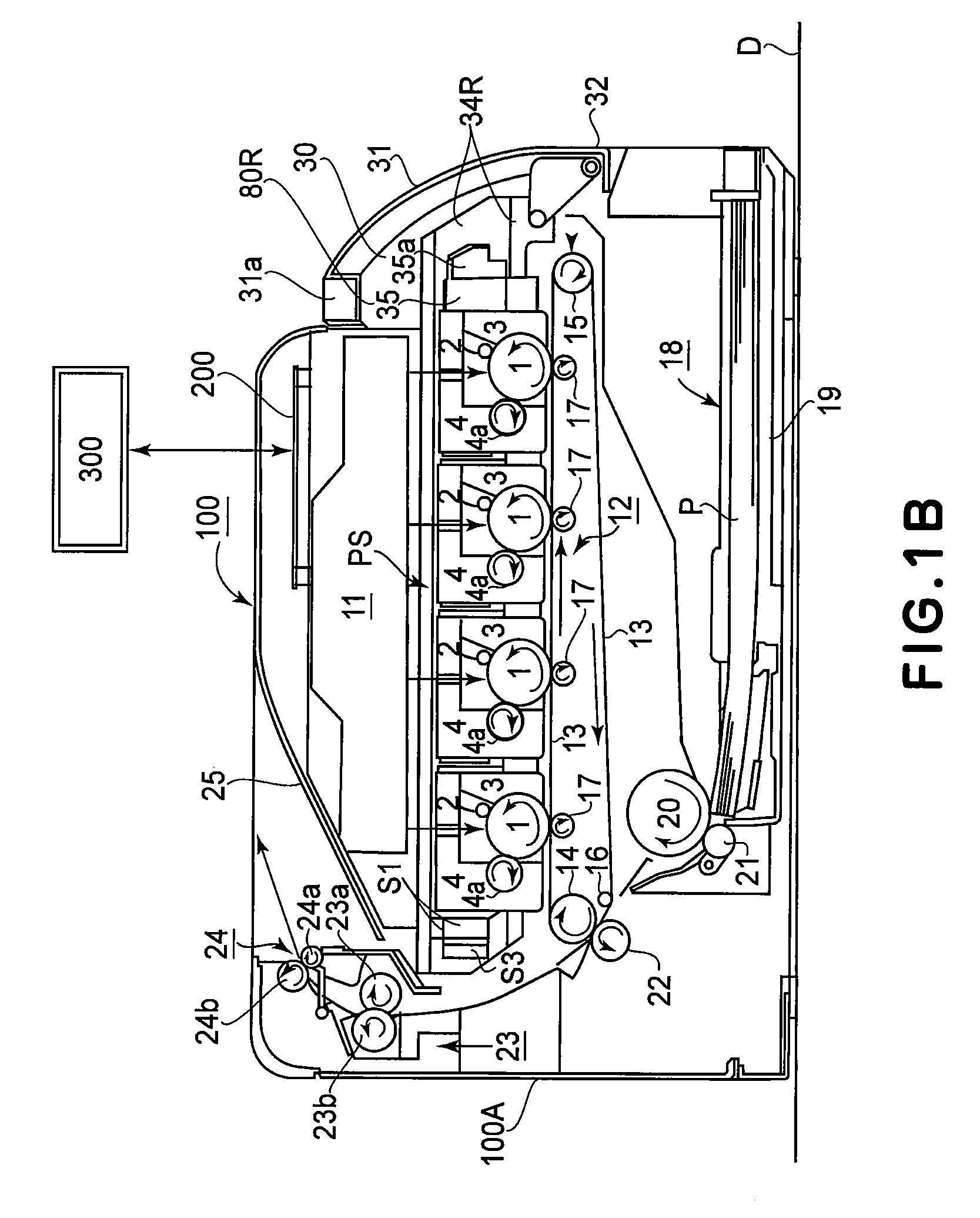
[0041]An electrophotographic image forming apparatus in this embodiment includes a rotatable electrophotographic photosensitive drum, an electrostatic latent image forming means for forming an electrostatic latent image on the drum, a developing means for developing with a developer the electrostatic latent image formed on the drum, and a transfer means for transferring a developer image formed on the drum. By these electrophotographic process means, the image is formed on a recording material (medium).

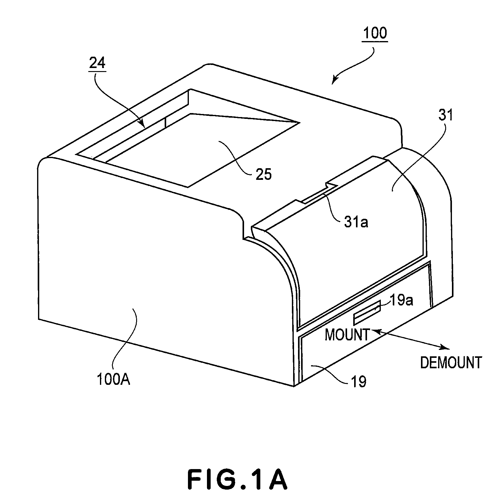
[0042]In the following description, a front side (front surface side) of the electrophotographic image forming apparatus means the side on which an apparatus opening / closing door (an opening / closing member) is provided. A rear side of the image forming apparatus is the side opposite to the front side. A front-rear direction includes a frontward direction toward front as seen from the rear side of the image...

embodiment 2

[Embodiment 2]

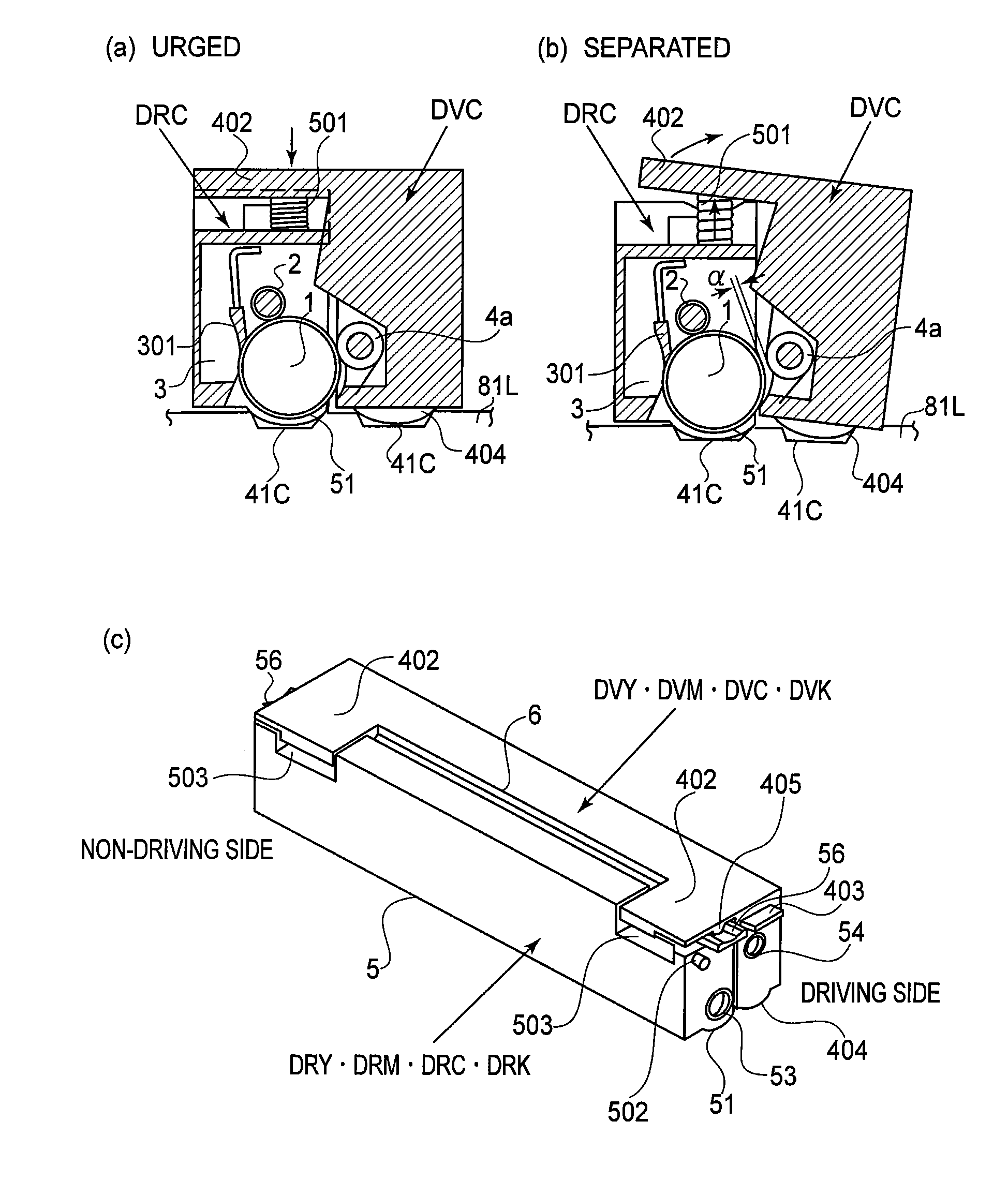
[0116]In Embodiment 2, as shown in FIG. 12(c) and FIG. 13(a), a grip 503 for gripping the cartridge DR by the user is provided to the cartridge DR and only the grip 503 is covered with the eave 402 of the cartridge DV. That is, the grip 503 provided to the cartridge DR is covered with the cartridge DV. Therefore, the demounting of the cartridge DR by using the grip 503 can only be performed after the cartridge DV is demounted in advance, so that the erroneous exchange by the user of the cartridge DV which does not reach the end of its lifetime is prevented. FIG. 12(c) shows a state in which the cartridge DR and the cartridge DV are placed on the tray 35 (not shown). FIG. 13(a) shows the cartridge DV alone. In this embodiment, the eave 402 as the preventing member is provided to the cartridge DV so as to project over an area connecting both longitudinal ends of the cartridge DR in the state in which the cartridge DR and the cartridge DV are supported by the tray 35. The...

embodiment 3

[Embodiment 3]

[0117]FIG. 13(b) and FIGS. 14(a) to 14(f) are schematic views for illustrating Embodiment 3. Description will be made by taking the set of the cartridge DRC and the cartridge DVC as an example but this is true for other sets of the cartridges. In this embodiment, in the state in which the cartridge DRC and the cartridge DVC are supported by the tray 35, a stopper shape portion 504 as the preventing member for preventing the cartridge DRC from being demounted from the tray 35 is provided to the cartridge DRC. The stopper shape portion 504 is provided so as to outwardly project from the outer surface of the drum cartridge frame 5. The cartridge DRC and the cartridge DVC are configured to be upwardly demounted from the tray 35 and the tray 35 is provided with the stay portion 35f as the engaging portion with the above-described stopper shape portion 504. FIG. 13(b) and FIG. 14(a) shows a state in which the tray 35 is pulled out to the outside position O and supports the c...


PUM


Abstract

An image forming apparatus for forming an image on a recording material in a state in which a drum cartridge including a photosensitive drum is detachably mountable to a main assembly of the apparatus and in a state in which a developing cartridge including a developing roller for developing with a developer an electrostatic latent image formed on the photosensitive drum and including a developer accommodating portion for accommodating the developer is detachably mountably to the main assembly, is constituted by a cartridge supporting member movable, in a state of detachably supporting the drum and developing cartridges, between an inside position in which the cartridge supporting member is located inside the main assembly and from which the drum and developing cartridges are movable to an image forming position in which the drum and developing cartridges effect image formation and an outside position in which the cartridge supporting member is located outside the main assembly and in which the drum and developing cartridges are mountable and demountable; and a preventing member, provided to the developing cartridge, for preventing demounting of the drum cartridge from the cartridge supporting member in a state in which the developing cartridge is supported by the cartridge supporting member.

Description

FIELD OF THE INVENTION AND RELATED ART[0001]The present invention relates to an electrophotographic image forming apparatus for effecting recording by developing with a developer a latent image formed on the electrophotographic photosensitive member and then transferring and fixing a developer image on a recording material (medium). The electrophotographic image forming apparatus employs the electrophotographic photosensitive member as an image bearing member to form an electrostatic latent image on the electrophotographic photosensitive member through an electrophotographic image forming process and forms an image on the recording material. For example, the electrophotographic image forming apparatus may include an electrophotographic copying machine, an electrophotographic printer (an LED printer, a laser beam printer, etc.), an electrophotographic facsimile machine, and an electrophotographic word processor. It is also possible to use a monochromatic or full-color image forming a...

Claims


Application Information

Patent Timeline
Patent Type & Authority Patents(United States)
IPC IPC(8): G03G15/00
CPCG03G21/1839G03G21/1853G03G21/1623G03G21/1642G03G21/1671G03G2221/1654G03G2221/1684G03G2221/1869
Inventor UCHIDA, WATARU
Owner CANON KK
Why Eureka
Try Eureka