
Pressure sensor with barrier providing impending sensor failure indication

a technology of impending sensor failure and pressure sensor, which is applied in the field of pressure sensors, can solve the problems of failure of the device, inability to install and maintain the device, and premature exchange of the device,

Inactive Publication Date: 2006-11-07
EHNDRESS KHAUZER GMBKH KO KG
View PDF13 Cites 15 Cited by
  • Summary
  • Abstract
  • Description
  • Claims
  • Application Information

AI Technical Summary

Benefits of technology

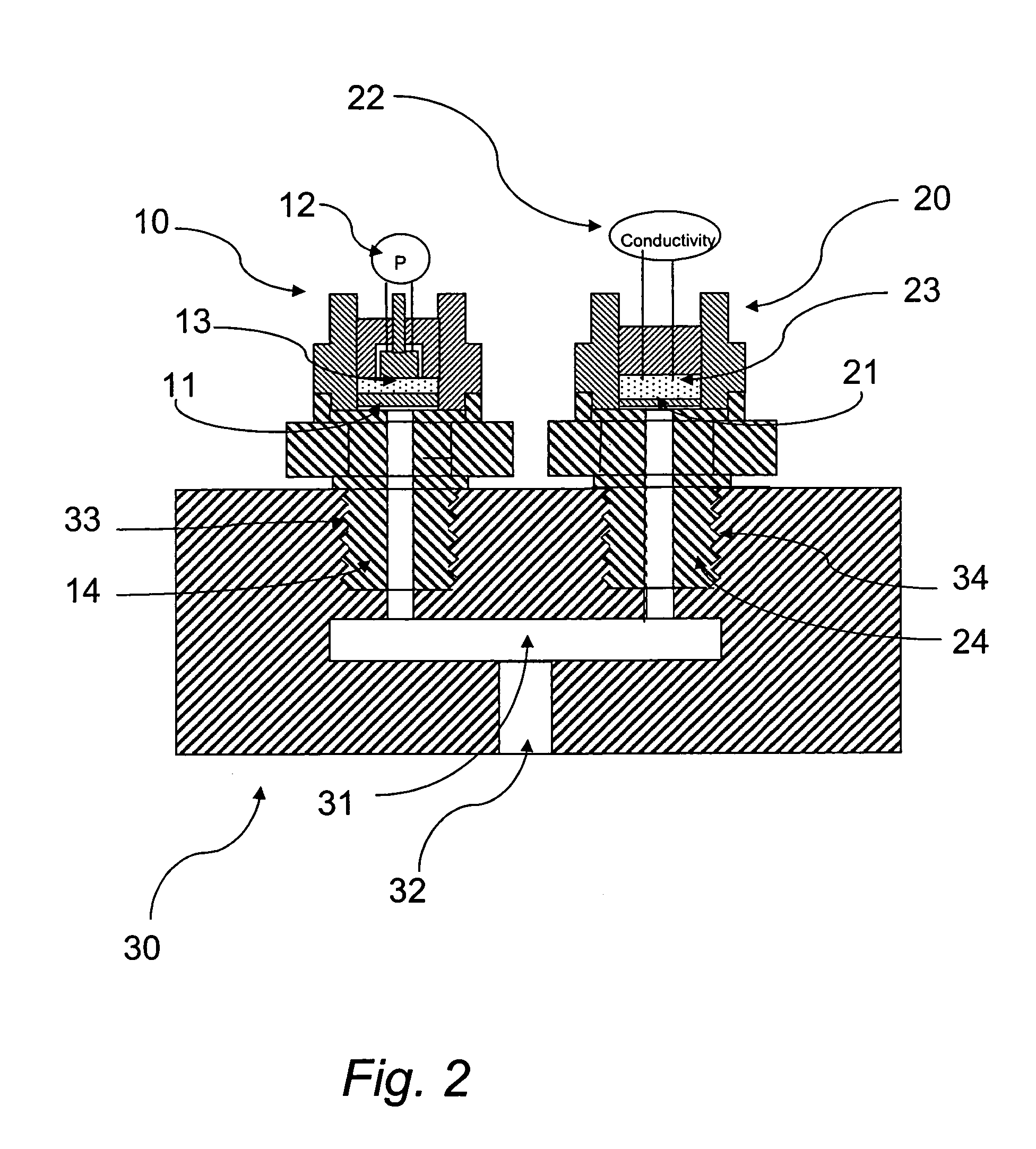
The present invention provides an improved device for early recognition of an impending membrane rupture. The device includes a platform, a first dividing membrane, a sensor chamber, and an early warning detector. The device allows for a flow connection between a sensor and a pressure measurement cell through the membrane. The detector monitors a property of a medium in the sensor chamber and is designed to fail faster than the membrane, allowing for a reliable prognosis about the membrane's remaining life span. The sensor can be a conductivity or capacitive sensor, and the device can be used in various industries to prevent unexpected stoppages of the installation.

Problems solved by technology

The described device has, however, the disadvantage that it ascertains a failure of the device only after the membrane rupture has already occurred and without having given any anticipatory warning that an exchange of the sensor was necessary.
This behavior frequently leads to unacceptable down times for the installation.
This can, however, lead in many instances to a premature exchange of the device, when actual membrane corrosion has not yet been so extensive that an exchange after the mentioned time is really needed.

Method used


Image

  • Pressure sensor with barrier providing impending sensor failure indication
  • Pressure sensor with barrier providing impending sensor failure indication
  • Pressure sensor with barrier providing impending sensor failure indication

Examples


Embodiment Construction

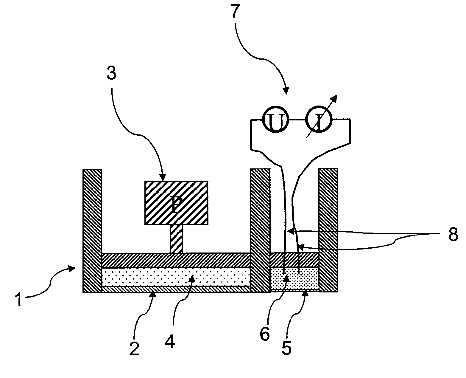
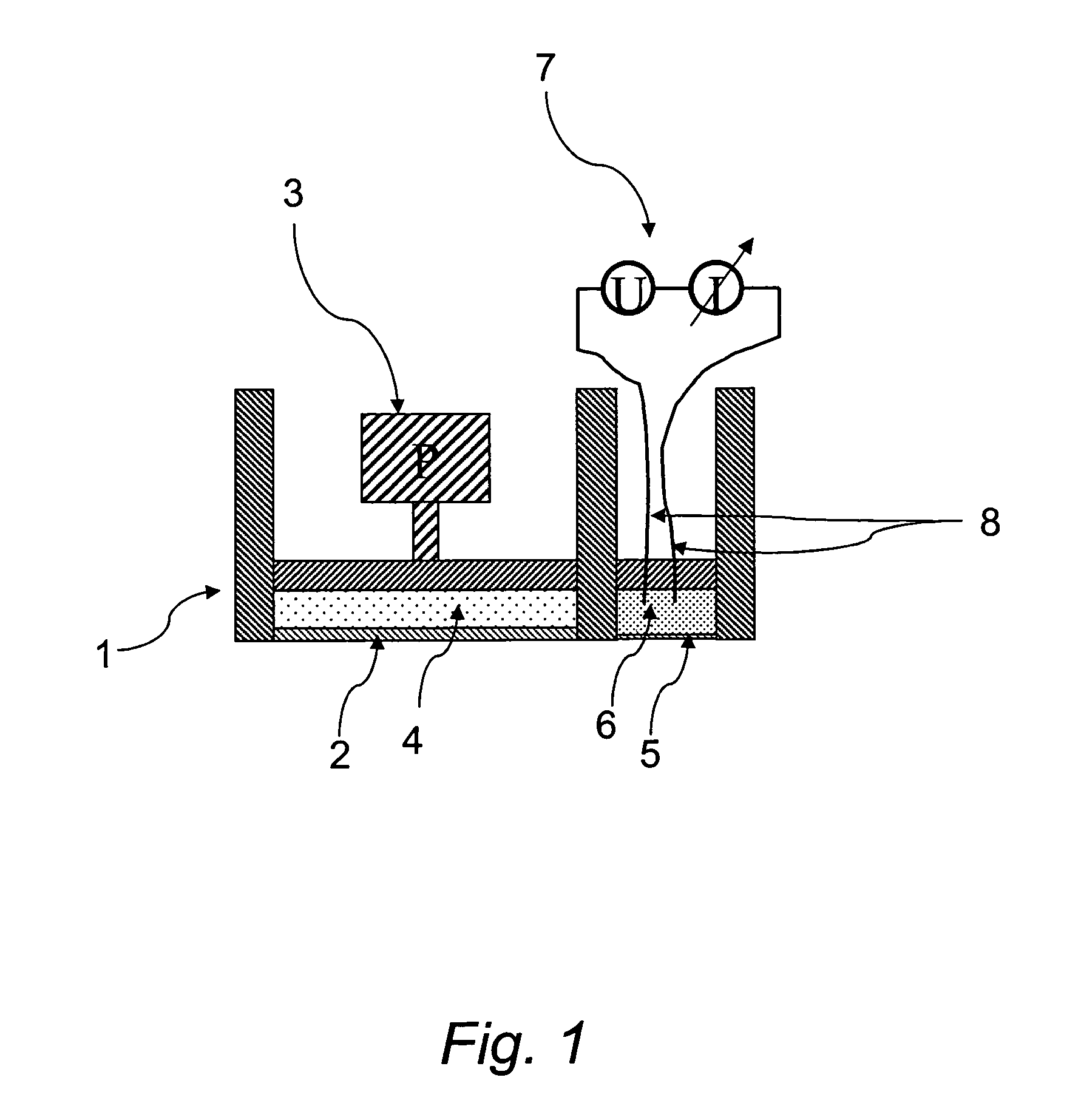
[0022]The pressure sensor shown in FIG. 1 includes a platform 1. A dividing membrane 2 is secured at its edge onto the front side of the platform, so that a pressure chamber 4 is formed between the dividing membrane 2 and the platform. In use, the dividing membrane is contacted on its side facing away from the pressure chamber with a first medium. The pressure chamber is filled with a second medium, the transfer medium, which preferably is a silicone oil. The transfer medium transmits the pressure to a pressure measurement cell 3, which produces a pressure-dependent measurement signal using any one of various methods known to those skilled in the art. This can occur, for example, capacitively, piezoresistively, inductively, or by a resonator method.

[0023]In the front side of the platform 1 next to the dividing membrane, a sacrificial membrane 5 is arranged, which preferably is made of the same material as the dividing membrane 2. The sacrificial membrane 5 is merely thinner than the...


PUM

PropertyMeasurementUnit
pressureaaaaaaaaaa
conductivityaaaaaaaaaa
corrosionaaaaaaaaaa

Abstract

A pressure transmitter for transfer of a pressure prevailing in a first medium onto a second medium, including a pressure chamber 4 in a platform 1, which chamber is separated from the first medium by means of a dividing membrane 2, wherein the pressure can be transferred by means of the second medium to a pressure measurement cell. For timely recognition of an impending failure of the dividing membrane, an early warning detector is provided with a sensor chamber 6 having an opening, which faces the first medium; and a sensor 7, which monitors a property of a medium container in the sensor chamber; and a barrier facing the first medium, pressure-tightly sealing the opening, and which, under contact with the first medium and equal conditions as experienced by the dividing membrane 2, fails earlier than the dividing membrane, thus making possible a flow connection between the sensor chamber 6 and the first medium. Preferably, the barrier is in the form of a sacrificial membrane 5, which is thinner than the dividing membrane. In this way, it is to be expected that, under corrosive destruction of the membranes, the sacrificial membrane 5 will be destroyed earlier than the dividing membrane 2.

Description

FIELD OF THE INVENTION[0001]The invention relates to a device for transferring a pressure from a pressure prevailing in a first medium onto a second medium.[0002]More specifically, the invention relates to devices having: a platform; a dividing membrane, which is secured at its edge onto the platform, wherein a first surface of the dividing membrane, facing away from the platform, can be brought into contact with the first medium, and a second surface of the dividing membrane, facing toward the platform, forms with the platform a pressure chamber, which can be filled with the second medium; and a sensor for ascertaining a rupture of the membrane.BACKGROUND OF THE INVENTION[0003]Devices of this type are, in addition to other uses, used for pressure measurement in aggressive media. The dividing membrane is contacted with an aggressive first medium and the pressure prevailing in the first medium is transferred to a second medium in the pressure chamber. There, the pressure is conducted...

Claims


Application Information

Patent Timeline
Patent Type & Authority Patents(United States)
IPC IPC(8): G01L7/08G01L7/18G01L19/12G01L9/12G01L1/00G01L19/06
CPCG01L19/0645G01L19/0672G01M3/16
Inventor TEXTOR, OLAF
Owner EHNDRESS KHAUZER GMBKH KO KG
Learn More