
Method and arrangement for monitoring the operating condition of a transport system

a technology for transport systems and operating conditions, applied in the direction of testing sensing arrangements, transportation and packaging, and elevators, etc., can solve the problems of inability to identify elevator passengers, difficult allocation of elevator calls, and failure to determine the location of elevator cars

Inactive Publication Date: 2014-10-09
KONE CORP
View PDF13 Cites 9 Cited by
  • Summary
  • Abstract
  • Description
  • Claims
  • Application Information

AI Technical Summary

Benefits of technology

The invention solution allows for regular monitoring of the reader device, even when there is no id reader nearby. This helps to detect any potential failure of the reader device quickly, and information can be sent to a service center for timely maintenance or replacement. This also increases the reliability of the reader device and improves its efficiency as a safety device, monitoring the movement of the elevator car and temporary safety spaces.

Problems solved by technology

Failure of a reader device in the aforementioned solutions would result in elevator passengers failing to be identified, in which case elevator calls would have to be given manually with separate call-giving devices.
Also the allocation of elevator calls would become more difficult if information about the identification data of elevator passengers was not available.
When the reader device fails, determination of the location of the elevator car no longer succeeds, in which case the elevator car might drive past a stopping floor or move outside the range of permitted movement of the elevator car.
One problem relating to the aforementioned solutions is that detecting failure of a reader device is difficult and repairing a defect is slow, because it can occur only on the basis of feedback received from a user of the elevator or as a consequence of a failure of the control system of the elevator.
Failure of the control system of an elevator additionally results in an interruption in the operation of the elevator.

Method used


Image

  • Method and arrangement for monitoring the operating condition of a transport system
  • Method and arrangement for monitoring the operating condition of a transport system
  • Method and arrangement for monitoring the operating condition of a transport system

Examples


Embodiment Construction

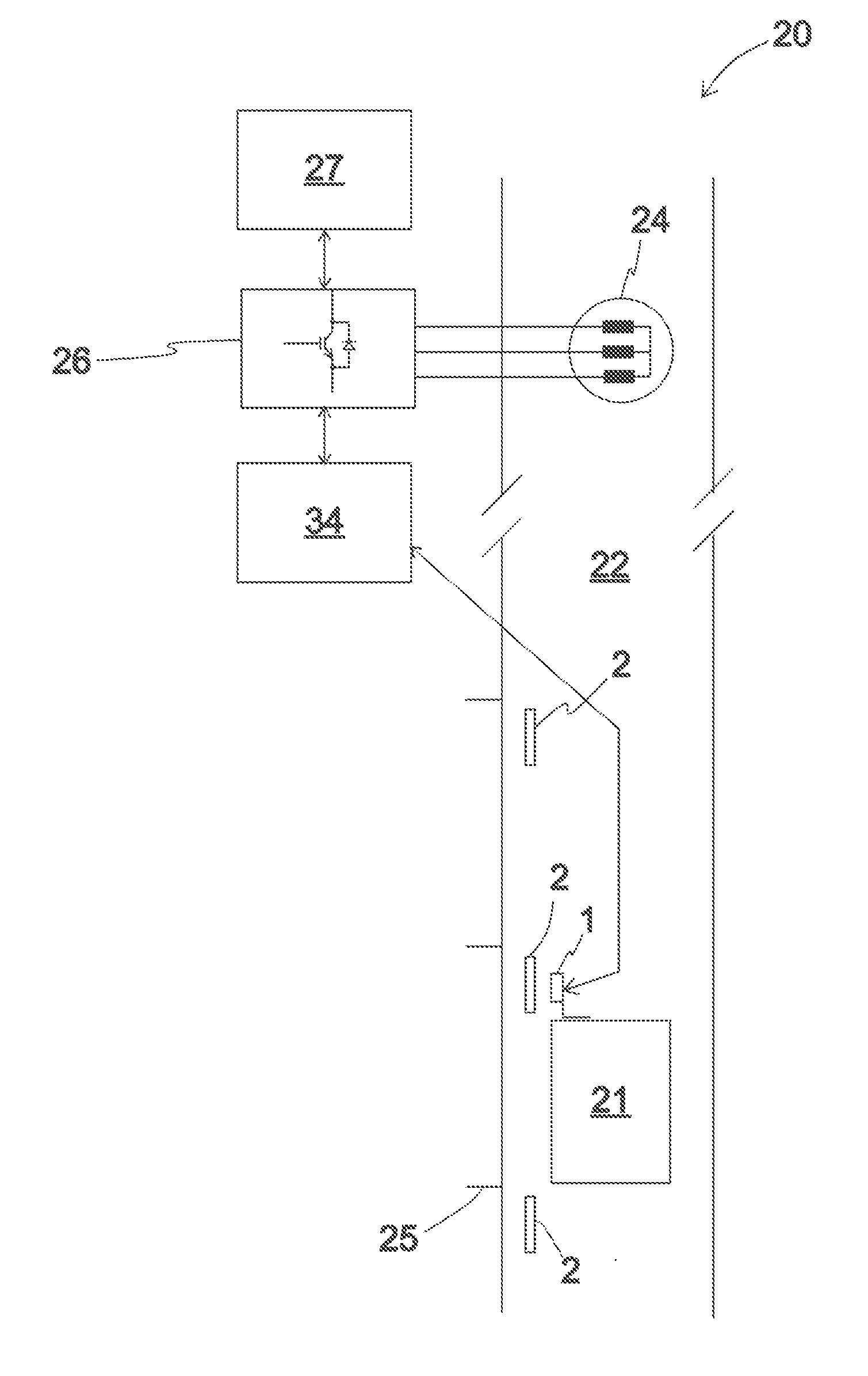
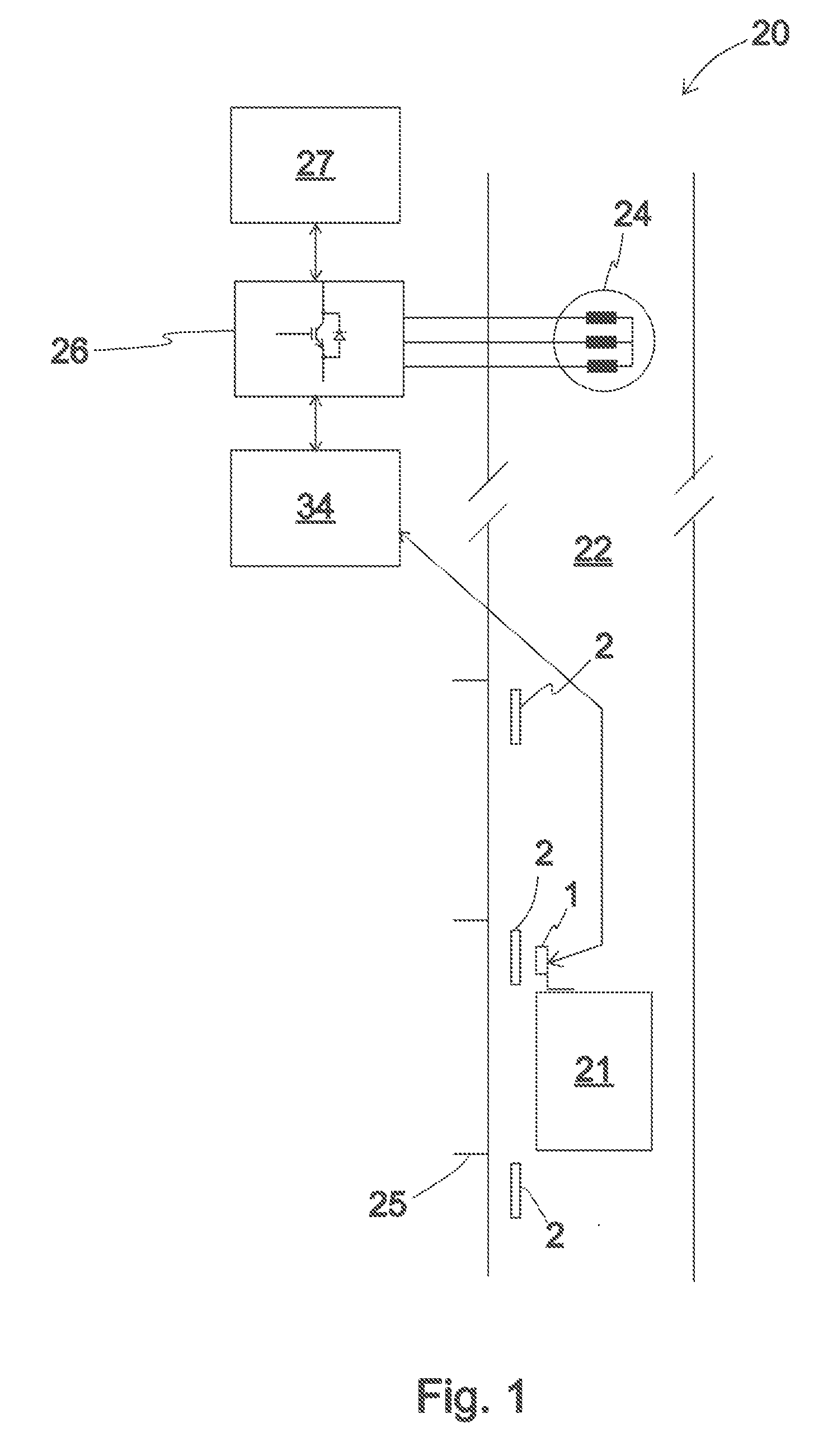
[0034]FIG. 1 presents an embodiment of an elevator system 20, in which the elevator car 21 is suspended in the elevator hoistway 22 with ropes, a belt or corresponding (not presented in FIG. 1) passing via the traction sheave of the hoisting machine 24 of the elevator. The elevator motor of the hoisting machine 24 of the elevator drives the elevator car 21 in the elevator hoistway 22 in an essentially vertical direction between floor levels 25 by rotating the traction sheave of the hoisting machine 24. The elevator control unit 27 calculates the target value for the speed of the elevator car 21, i.e. the speed reference, according to which the elevator car is moved in the elevator hoistway in the manner required by elevator calls. A frequency converter 26 adjusts the speed of the traction sheave, and thereby the speed of the elevator car 21, towards the speed reference by adjusting the current of the elevator motor. An elevator call can include information about the departure floor ...


PUM


Abstract

The invention relates to a method and arrangement for monitoring the operating condition of a transport system. In the method a reader device is fitted to the transport system, which reader device is configured to read an identifier that is separate from the reader device and is provided with a readable marking when the identifier is situated within range of the reading signal of the reader device, measuring means are fitted in connection with the reader device for measuring the operation of the reader device, the operation of the reader device is measured in connection with a reading procedure being performed, and also a functional nonconformance of the reader device is determined on the basis of the measurement of the operation of the reader device.

Description

[0001]This application is a continuation of PCT International Application No. PCT / FI2013 / 050056 which has an International filing date of Jan. 18, 2013, and which claims priority to Finnish patent application number 20125072 filed Jan. 23, 2012, the entire contents of both which are incorporated herein by reference.FIELD OF THE INVENTION[0002]The invention relates to solutions for monitoring the operating condition of a reader device reading an identifier provided with a readable marking.BACKGROUND OF THE INVENTION[0003]Various solutions exist wherein a reader device is used to read different identifiers that are separate from the reader device. In some solutions the reader device is configured to read an identifier that is separate from the reader device and is provided with a readable marking when the identifier is situated within range of the reading signal of the reader device. In some solutions RFID identifiers are read with a reader device. In this case the reader device usual...

Claims


Application Information

Patent Timeline
IPC IPC(8): B66B3/02
CPCB66B3/02B66B5/0018G06K7/0095B66B5/0012
Inventor KANGAS, PETTERIHAAKSLUOTO, VILLE
Owner KONE CORP
Learn More