Spindle support bracket

a technology for supporting brackets and spindles, which is applied in the direction of machine supports, other domestic objects, transportation and packaging, etc., can solve the problems of prior art worthless or in effect, and achieve the effect of limiting the ability of said spindle and preventing lateral movement of said spindl

Inactive Publication Date: 2007-09-18
KAROLY JOHN
View PDF47 Cites 14 Cited by
  • Summary
  • Abstract
  • Description
  • Claims
  • Application Information

AI Technical Summary

Benefits of technology

[0063]This new bracket which to do the job at hand requires two brackets, is very portable. That is why an invention of this nature needs to be available to all trades that require a support bracket for a spindle that reels and/or spools are placed on. Another advantage of the new bracket is that the said spindle, with nothing but gravity pulling down on it, becomes bound by the spindle supports, limiting the ability of said spindle from rotating with the spools or reels and preventing a lateral movement of the said spindl

Problems solved by technology

In so much that the said spindle(s) would not have to have exact dimensions, nor would it have to have, clips, pins, bores, or other devices or attachments, that might get lo

Method used


Image

  • Spindle support bracket
  • Spindle support bracket
  • Spindle support bracket

Examples


Embodiment Construction

[0101]The following discussion describes in detail one embodiment of the invention (and several variations of that embodiment). This discussion should not be construed, however, as limiting the invention to those particular embodiments, practitioners skilled in the art will recognize numerous other embodiments as well. For definition of the complete scope of the invention, the reader is directed to appended claims.

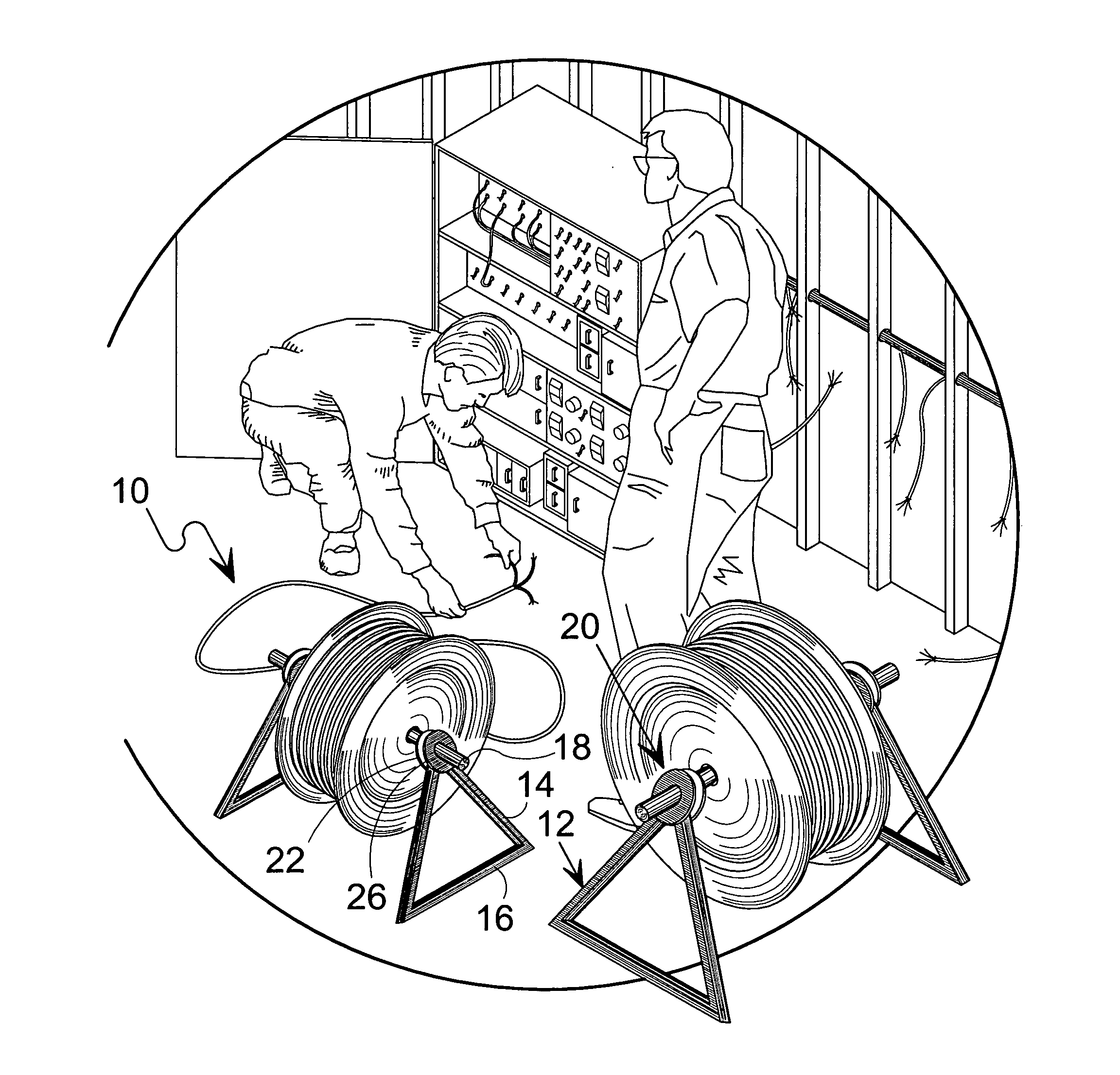
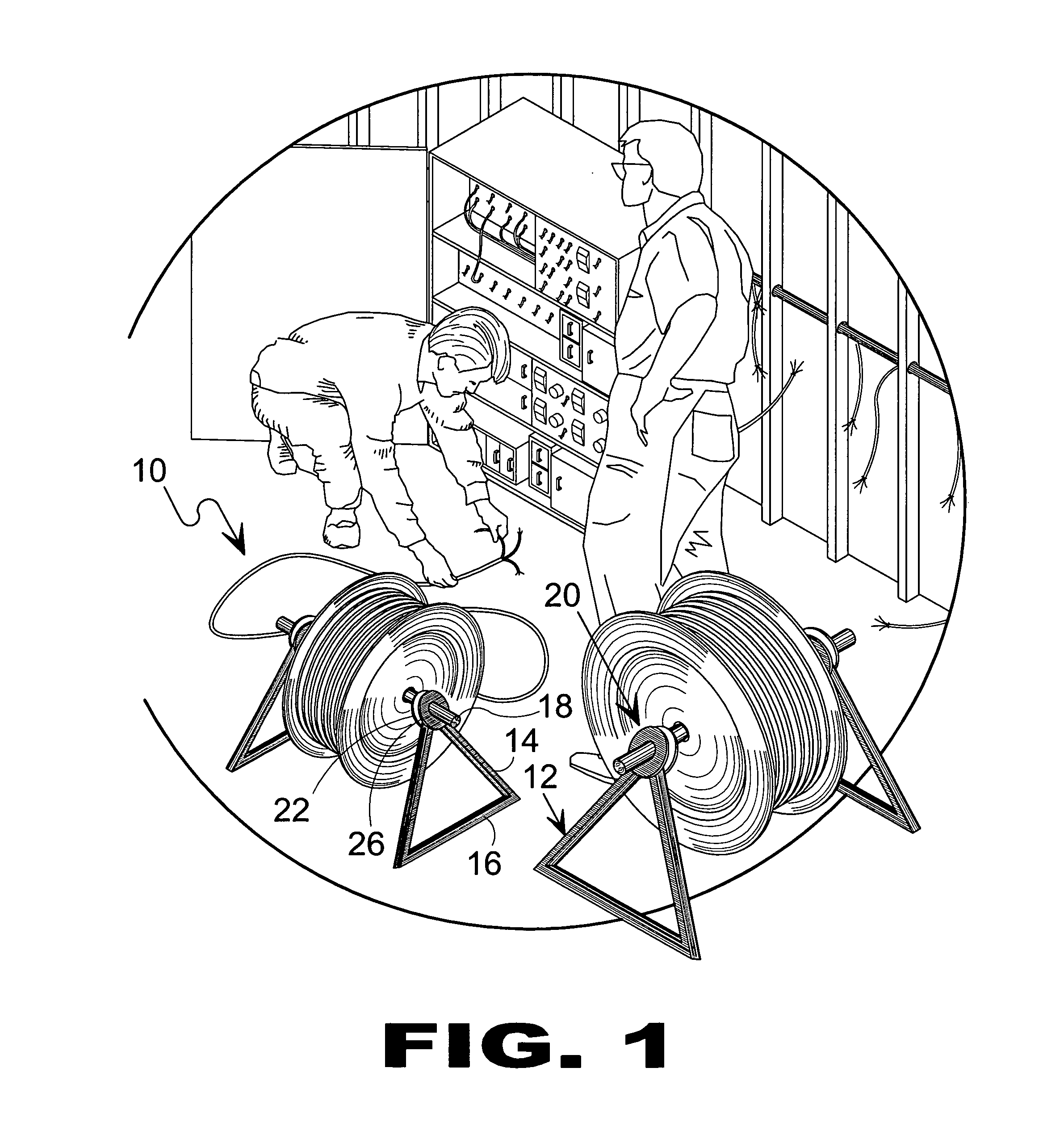
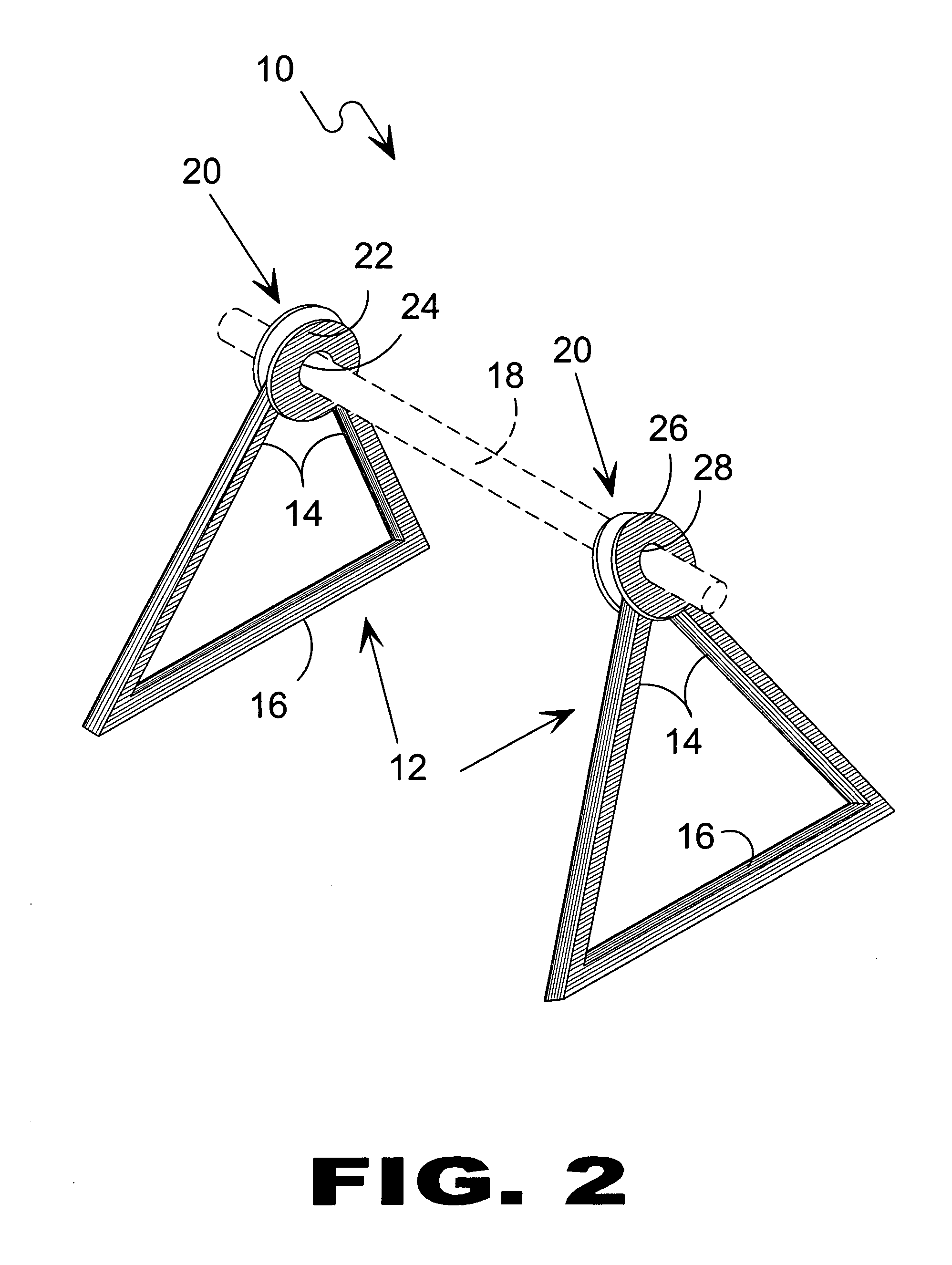
[0102]Referring to FIG. 1, shown is an illustrative view of the present invention in use. Shown is the spindle support system 10 of the present invention in use to support a cable spool. The present invention comprises the use of at least two spindle support members 10 to suspend the spindle 18 by supporting each end thereof on opposing sides of the spool. The spindle support 10 is comprised of frame 12 comprising legs 14 and base 16 with spindle support 20 fixed thereto. Spindle support 20 has opposing support members 22 and 26 with apertures for receiving spindle 18.

[010...


PUM


Abstract

The present invention is a stand used for supporting a reel of wound material typically wire, by means of a spindle extending through a reel that is supported at either end by spindle support members having a triangular form and with at least one angled receiving aperture made through a corner having a collar, whereby when assembled produces a horizontally disposed spindle supported by opposing inwardly angled triangular support members where said spindle ends are supported about said support members apexes.

Description

RELATED APPLICATIONS[0001]This application is subject to U.S. provisional application Ser. No. 60 / 664,583; filed 23 Mar. 2005. Please incorporate by reference all information in said provisional application into this instant application.BACKGROUND OF THE INVENTION[0002]1. Field of the Invention[0003]The present invention relates generally to the supporting of a spindle that reels or spools are placed on for dispensing of materials that are purchased on a reel or spool (i.e. wire, tubing, rope string etc.) And more specifically to a very portable bracket that would be generally used in field applications that require the above mentioned spindle to be frequently and / or readily moved to accommodate the dispensing of materials in various, space limited and many locations, in which a permanent or fixed support would not be available or feasible.[0004]Various holders have been designed for spools, in order to make access, handling, and unwinding of wire easier. Marcell (U.S. Pat. No. 3,99...

Claims


Application Information

Patent Timeline
IPC IPC(8): B65H75/18
CPCB65H49/321
Inventor KAROLY, JOHN
Owner KAROLY JOHN
Why Eureka
Try Eureka