
Electrical connector with load bearing features

a technology of load bearing and electrical connector, which is applied in the direction of coupling contact members, fixed connections, coupling device connections, etc., can solve the problems of preventing a full connection with the printed circuit board, damage to the contact block and electrical connector,

Inactive Publication Date: 2007-09-18
FCI AMERICAS TECH LLC
View PDF110 Cites 34 Cited by
  • Summary
  • Abstract
  • Description
  • Claims
  • Application Information

AI Technical Summary

Benefits of technology

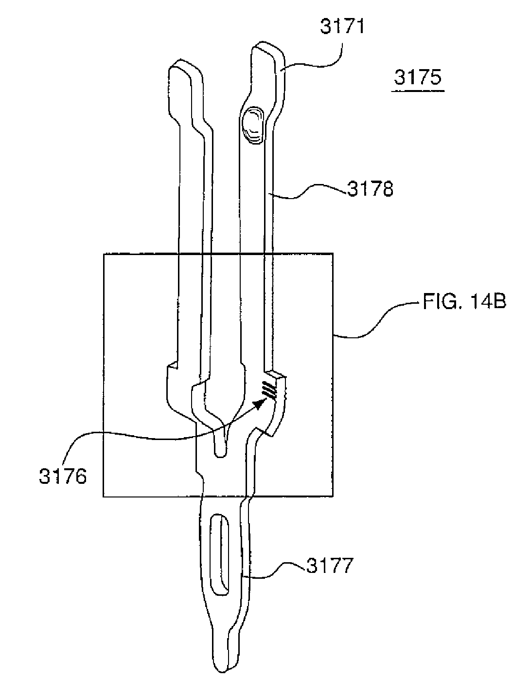
[0007]An embodiment of the invention includes complementary contact and contact block designs that help prevent movement of a contact received in the contact block when an electrical connector is press-fit or otherwise connected to a printed circuit board or other substrate. A protrusion may be included on one or both beams of a dual beam contact, and a contact cavity may be formed in the contact block. The protrusion and the contact cavity may include complementary shapes such that the protrusion abuts a wall within the contact cavity, preventing the contact from moving relative to the contact block as the electrical connector is press-fit or otherwise connected to a printed circuit board. The protrusion and a wall of the contact cavity additionally may include other complementary shapes (e.g., a radius or angle shape) such that a length of the protrusion abuts the contact cavity wall, providing a longer load bearing surface. The longer load bearing surface may provide additional support to the connector, further preventing the contact from moving relative to the contact block when a connector is connected to a printed circuit board. The protrusion may include a retention surface, such as barbs or ribs, that bite into the contact block for added support.

Problems solved by technology

A problem may arise when press-fitting an electrical connector to a printed circuit board where the contacts are not encapsulated within a contact block during molding of the contact block.
That is, as a force is applied on the electrical connector, pressing the connector onto the printed circuit board, the contacts may not fully engage with the printed circuit board and instead may move within the contact block, potentially causing damage to the contact block and electrical connector, and preventing a full connection with the printed circuit board.

Method used


Image

  • Electrical connector with load bearing features
  • Electrical connector with load bearing features
  • Electrical connector with load bearing features

Examples


Embodiment Construction

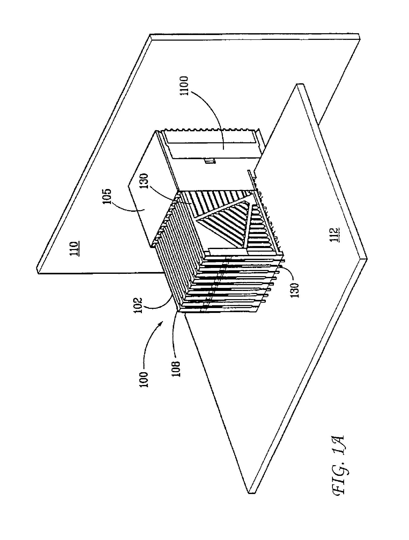
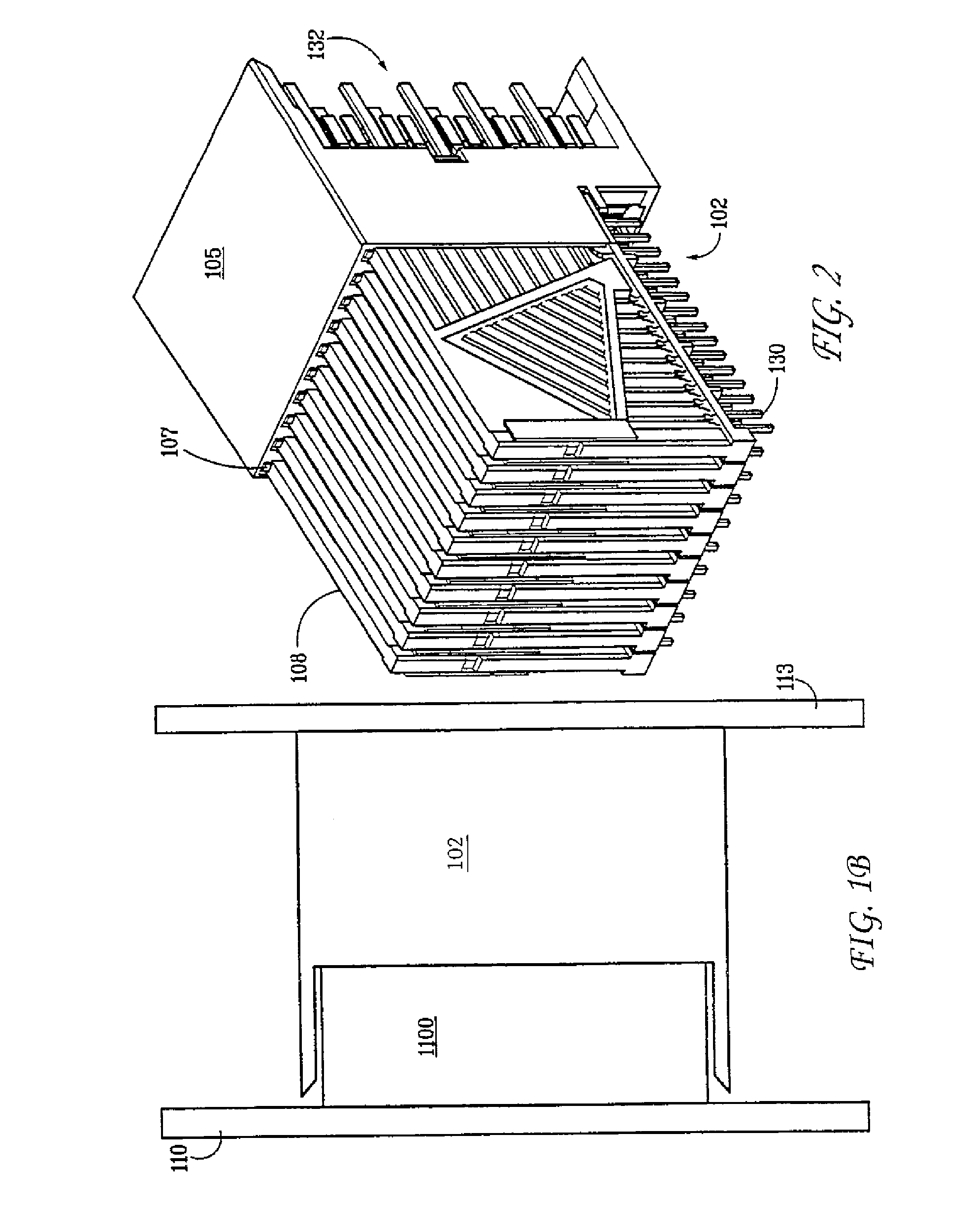
[0024]FIG. 1A is a perspective view of a backplane system 110 having an exemplary right angle electrical connector 100 in accordance with an embodiment of the invention. However, the invention may take other forms such as a vertical or horizontal electrical connector. As shown in FIG. 1A, connector 100 comprises a plug connector 102 and receptacle connector 1100.

[0025]Plug connector 102 comprises housing 105 and a plurality of lead assemblies 108. The housing 105 is configured to contain and align the plurality of lead assemblies 108 such that an electrical connection suitable for signal communication is made between a first electrical device 112 and a second electrical device 110 via receptacle connector 1100. In one embodiment of the invention, electrical device 110 is a backplane and electrical device 112 is a daughter card. Electrical devices 110 and 112 may, however, be any electrical device without departing from the scope of the invention.

[0026]As shown, the connector 102 com...


PUM


Abstract

Complementary contact and contact block designs are disclosed that help prevent movement of a contact received in the contact block when an electrical connector is press-fit or otherwise connected to a printed circuit board. A protrusion may be included on one or both beams of a dual beam contact, and a contact cavity may be formed in the contact block. The protrusion and the contact cavity may include complementary shapes such that the protrusion abuts a wall within the contact cavity, preventing the contact from moving relative to the contact block as the electrical connector is connected to a printed circuit board. The protrusion and a wall of the contact cavity additionally may include other complementary shapes (e.g., a radius or angle shape) such that a length of the protrusion abuts the contact cavity wall, providing a longer load bearing surface.

Description

CROSS REFERENCE TO RELATED APPLICATIONS[0001]The present application is a continuation-in-part of U.S. patent application having Ser. No. 10 / 232,883 filed Aug. 30, 2002 now U.S. Pat. No. 6,899,548, entitled “Electrical Connector Having A Cored Contact Assembly,” which is assigned to the assignee of the present application and hereby incorporated herein by reference in its entirety.[0002]The present application is related to U.S. patent application having Ser. No. 10 / 232,353 filed Aug. 30, 2002, entitled “Connector Receptacle Having A Short Beam And Long Wipe Dual Beam Contact,” which is assigned to the assignee of the present application and hereby incorporated herein by reference in its entirety.FIELD OF THE INVENTION[0003]The invention relates to electrical connectors and specifically to electrical connectors in which electrical contacts are inserted into the connector or a contact block of the connector during connector assembly.BACKGROUND OF THE INVENTION[0004]Electrical connect...

Claims


Application Information

Patent Timeline
Patent Type & Authority Patents(United States)
IPC IPC(8): H01R13/648H01L21/00H01R13/652H01R12/16H01R12/55H01R13/11H01R13/405
CPCH01R12/585H01R13/41H01R13/112
Inventor HOUTZ, TIMOTHY W.
Owner FCI AMERICAS TECH LLC
Learn More