
Contact less charger with alignment indicator

a charger and alignment indicator technology, applied in the direction of electric vehicles, transportation and packaging, electric generators, etc., can solve the problems of time-consuming product design and high manufacturing cos

Active Publication Date: 2007-09-18
GOOGLE TECHNOLOGY HOLDINGS LLC
View PDF11 Cites 132 Cited by
  • Summary
  • Abstract
  • Description
  • Claims
  • Application Information

AI Technical Summary

Problems solved by technology

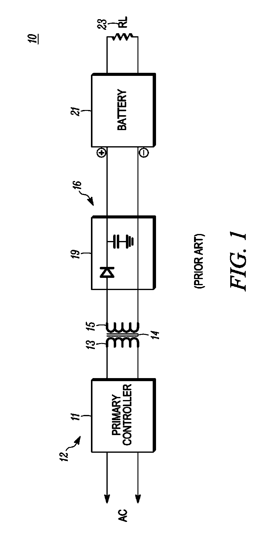
One problem that plagues most contactless chargers is aligning the secondary coil with the primary coil so as to couple the most magnetic flux to the secondary, thereby ensuring the most efficient charging process.
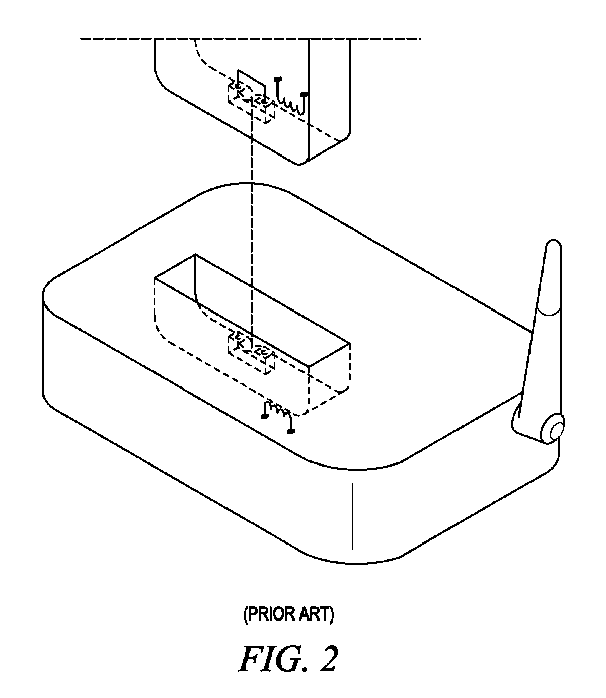
The problem with the lock and key solution is that a unique charger must be specifically designed for each electronic device.
This specialization of chargers makes the product time consuming to design and expensive to manufacture.

Method used


Image

  • Contact less charger with alignment indicator
  • Contact less charger with alignment indicator
  • Contact less charger with alignment indicator

Examples


Embodiment Construction

[0016]A preferred embodiment of the invention is now described in detail. Referring to the drawings, like numbers indicate like parts throughout the views. As used in the description herein and throughout the claims, the following terms take the meanings explicitly associated herein, unless the context clearly dictates otherwise: the meaning of “a,”“an,” and “the” includes plural reference, the meaning of “in” includes “in” and “on.”

[0017]Turning now to FIGS. 3 and 4, illustrated therein is a visual representation of the coupling between a primary 300 and secondary 301 of an inductive charging system. FIGS. 3 and 4 illustrate just why alignment is important in a contactless charging system. In FIG. 3, the primary 300 and secondary 301 are aligned, while in FIG. 4 the primary 300 and secondary 301 are misaligned relative to an efficient charging process.

[0018]The primary 300 includes a wire 304 that is coiled about a core 302. The core 302 is optional, in that some primary windings u...


PUM

PropertyMeasurementUnit
shapeaaaaaaaaaa
magnetic fluxaaaaaaaaaa
currentaaaaaaaaaa

Abstract

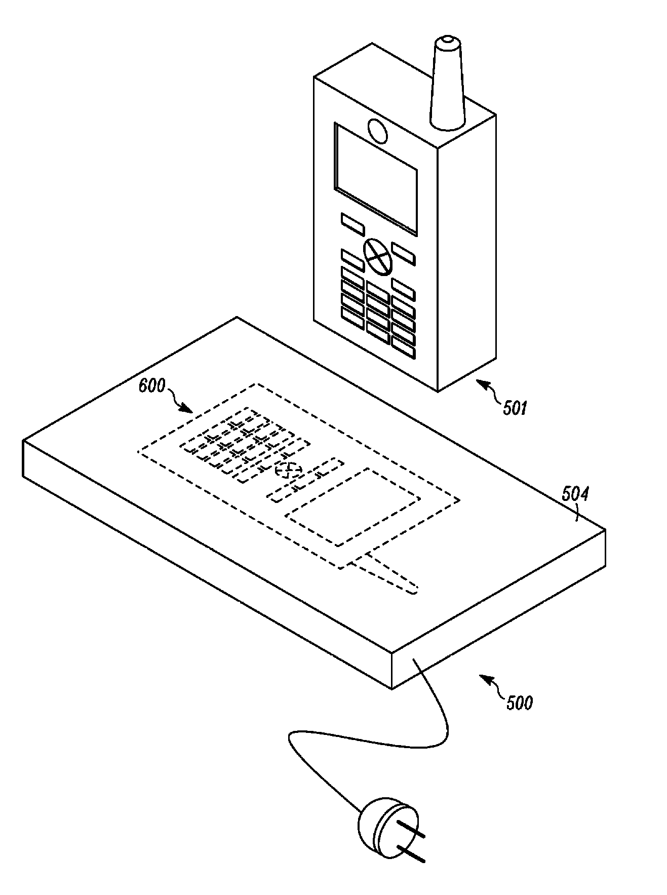
A contactless, inductive charger having a generally planar surface is provided. An image, text or other visual indicator is disposed upon the substantially planar surface such that the visual indicator represents a preferred placement orientation for an electronic device for optimal inductive charging. The charger includes a primary coil positioned within the boundaries of the image, such that a user has a visual guide for placing the device on the charging surface for maximum efficiency in charging. The visual indicator, which may be a picture, outline, text or other directional indicator, may be geometrically similar to a shape of the electronic device or may be in the shape of a generic device. It may be disposed upon the charger by a method selected from the group consisting of painting, molding, silk screening, plating, vapor deposition and adhesive retention.

Description

BACKGROUND[0001]1. Technical Field[0002]This invention relates generally to the field of contactless battery chargers for portable devices, and more particularly to a contactless charger with an alignment indicator to facilitate efficient charging.[0003]2. Background Art[0004]Contactless, or inductive, electrical connections are well known in the field of portable electrical devices. For example, portable, motorized toothbrushes typically contain a rechargeable battery which is charged by an inductive connection. Similarly, portable wireless communication devices, such as two-way RF radios, cellular phones, paging devices, and wireless communicators, commonly utilize a rechargeable battery that, in certain applications, is recharged by contactless, induction charging.[0005]Most all contactless chargers charge batteries by induction. Current, passed through a coil, creates a magnetic flux in accordance with Ampere's law. When a second coil is placed in close proximity to such a curre...

Claims


Application Information

Patent Timeline
Patent Type & Authority Patents(United States)
IPC IPC(8): H01M10/46
CPCH02J7/025H02J7/0044H02J7/0042H02J50/90H02J50/10
Inventor OGLESBEE, JOHN WENDELL
Owner GOOGLE TECHNOLOGY HOLDINGS LLC
Learn More