

Electroluminescent sign
a technology of electroluminescent lamps and display signs, which is applied in the direction of discharge tubes, luminescent screens, instruments, etc., can solve the problems of light/power loss, affecting the final shape and size of electroluminescent lamps, and complicating the lamp production process, so as to facilitate the application of various layers
- Summary
- Abstract
- Description
- Claims
- Application Information
AI Technical Summary
Benefits of technology
Problems solved by technology
Method used
Image

Examples
Embodiment Construction
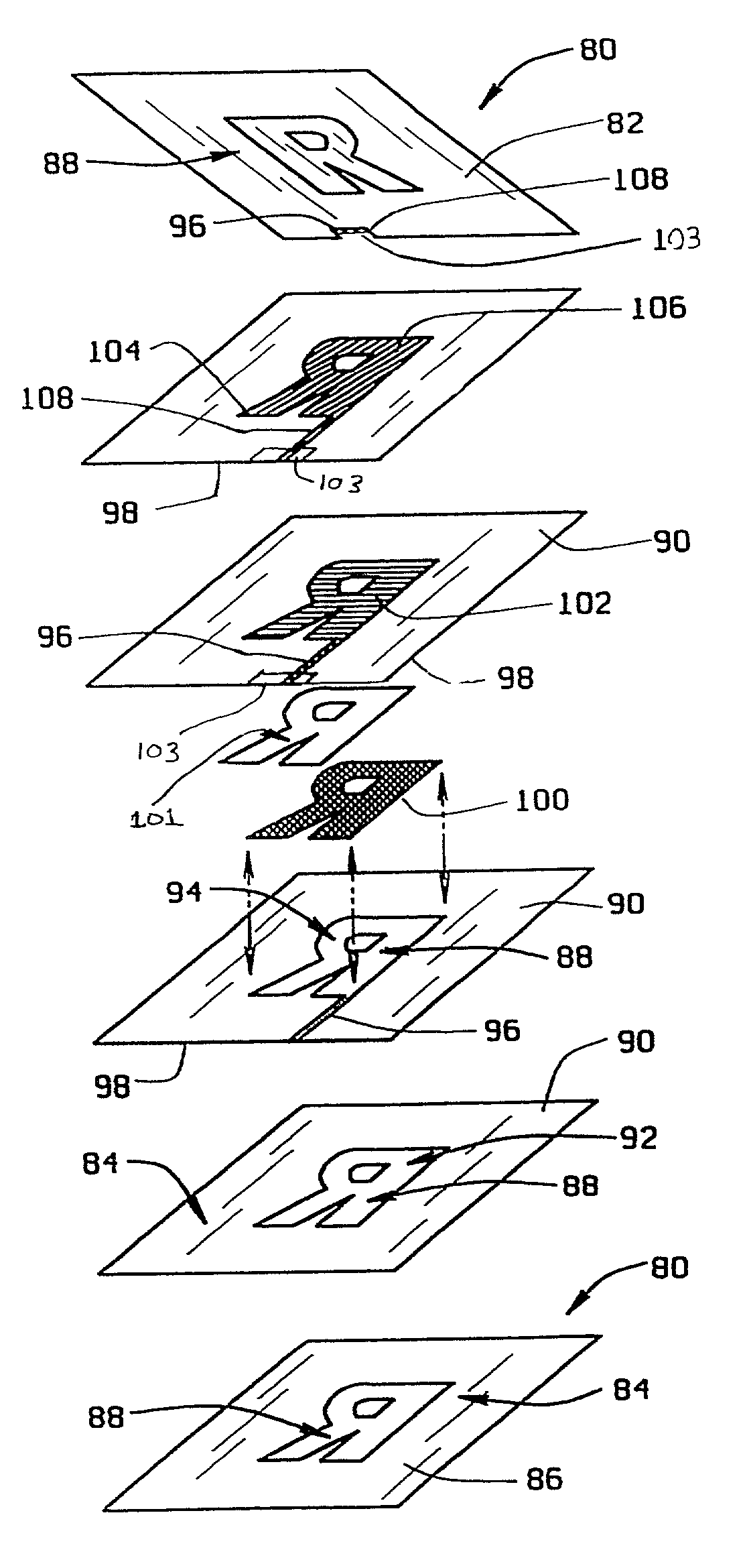
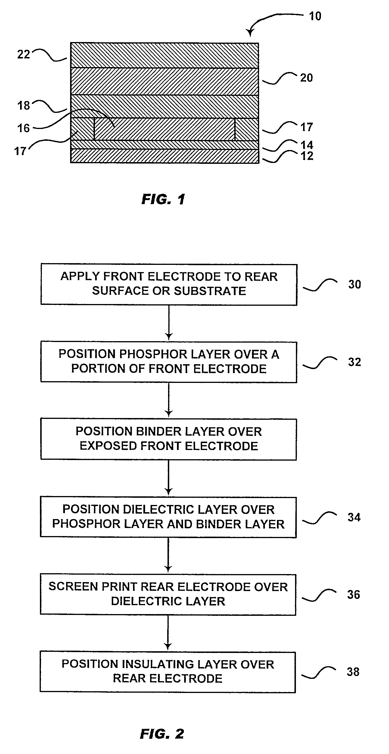
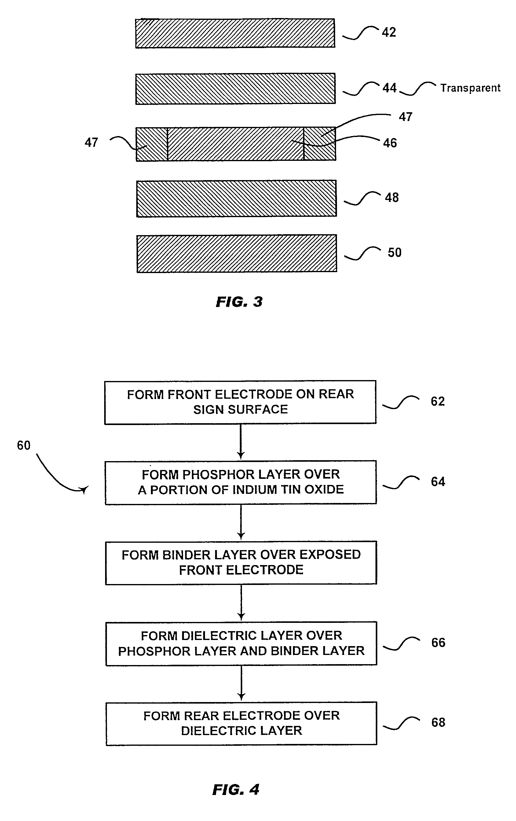
[0024]FIG. 1 is a schematic illustration of one embodiment of an electroluminescent (EL) lamp 10 of the present invention. The electroluminescent lamp 10 includes a substrate 12 having a coating of light-transmissive conductive material, a front electrode 14, a phosphor layer 16, a sealant layer 17, a dielectric layer 18, a rear electrode 20 of conductive particles, and a protective coating layer 22. Substrate 12 may, for example, be a polyethylene terephthalate) (PET) film coated with indium tin oxide. Front electrode 14 is preferably formed from silver particles. Phosphor layer 16 may be formed of electroluminescent phosphor particles, e.g., zinc sulfide doped with copper or manganese which are dispersed in a polymeric binder. Dielectric layer 18 may be formed of high dielectric constant material, such as barium titanate dispersed in a polymeric binder. Rear electrode 20 is formed of conductive particles, e.g., silver or carbon, dispersed in a polymeric binder to form a screen pri...
PUM
 Abstract
Description
Claims
Application Information