
Leg-wide connection admission control

Inactive Publication Date: 2007-09-18
NOKIA SOLUTIONS & NETWORKS OY
View PDF20 Cites 1 Cited by
  • Summary
  • Abstract
  • Description
  • Claims
  • Application Information

AI Technical Summary

Benefits of technology

[0013]According to the present invention, connection establishment is performed both faster and conceptually clearer than in the conventional method. The present invention eliminates the disadvantages of the conventional connection admission control by reducing the number of messages upon accepting a leg of a through switch connection and by making the leg more natural for the connection admission control.

Problems solved by technology

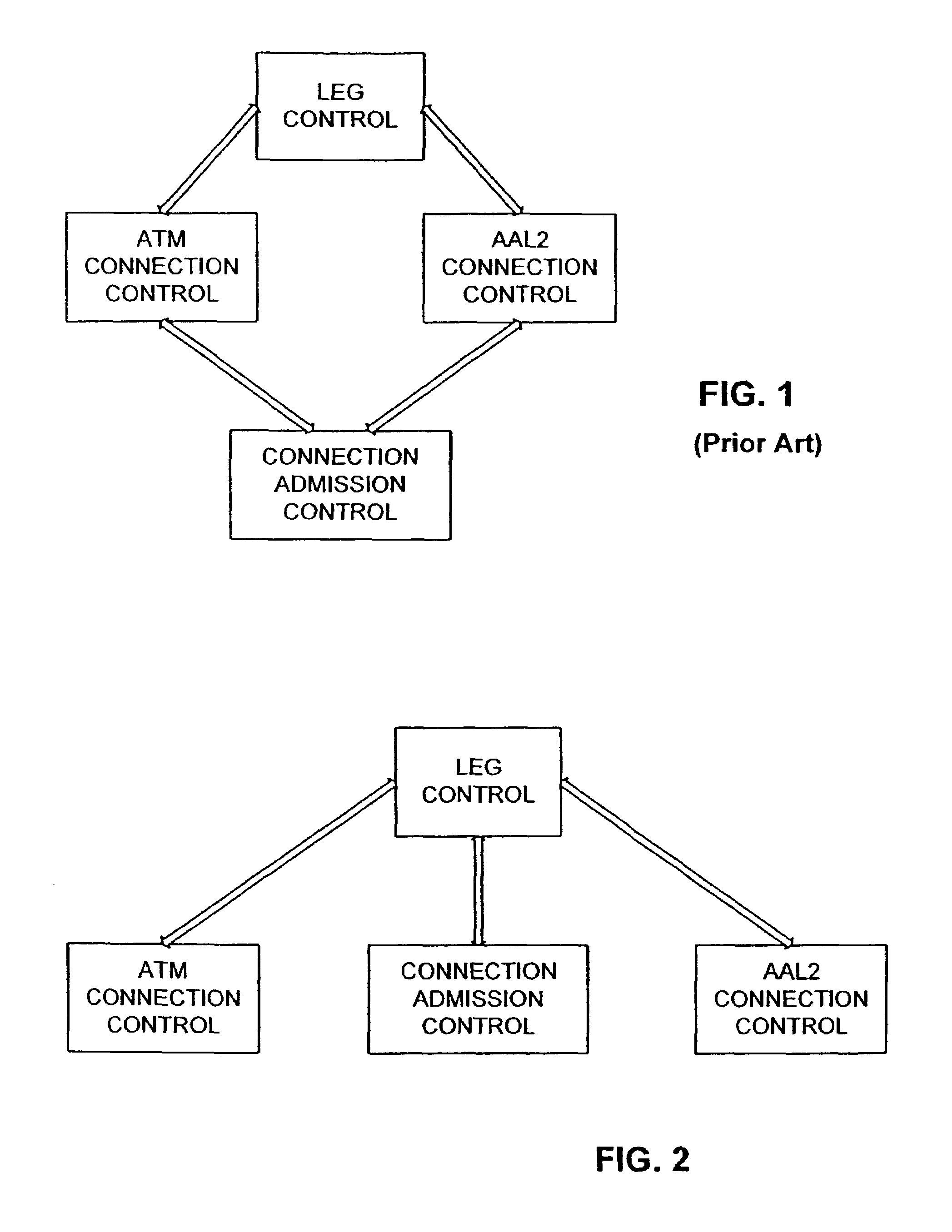
However, this conventional way of providing connection admission control is ineffective since many messages have to be exchanged in order to accept each connection being part of a leg.
Moreover, when connection admission control accepts for example an AAL2 connection, this does not mean that the other connections forming the leg are acceptable by the connection admission control.
Thus, the conventional connection admission procedure is both ineffective and conceptually difficult.

Method used


Image

  • Leg-wide connection admission control
  • Leg-wide connection admission control
  • Leg-wide connection admission control

Examples


Embodiment Construction

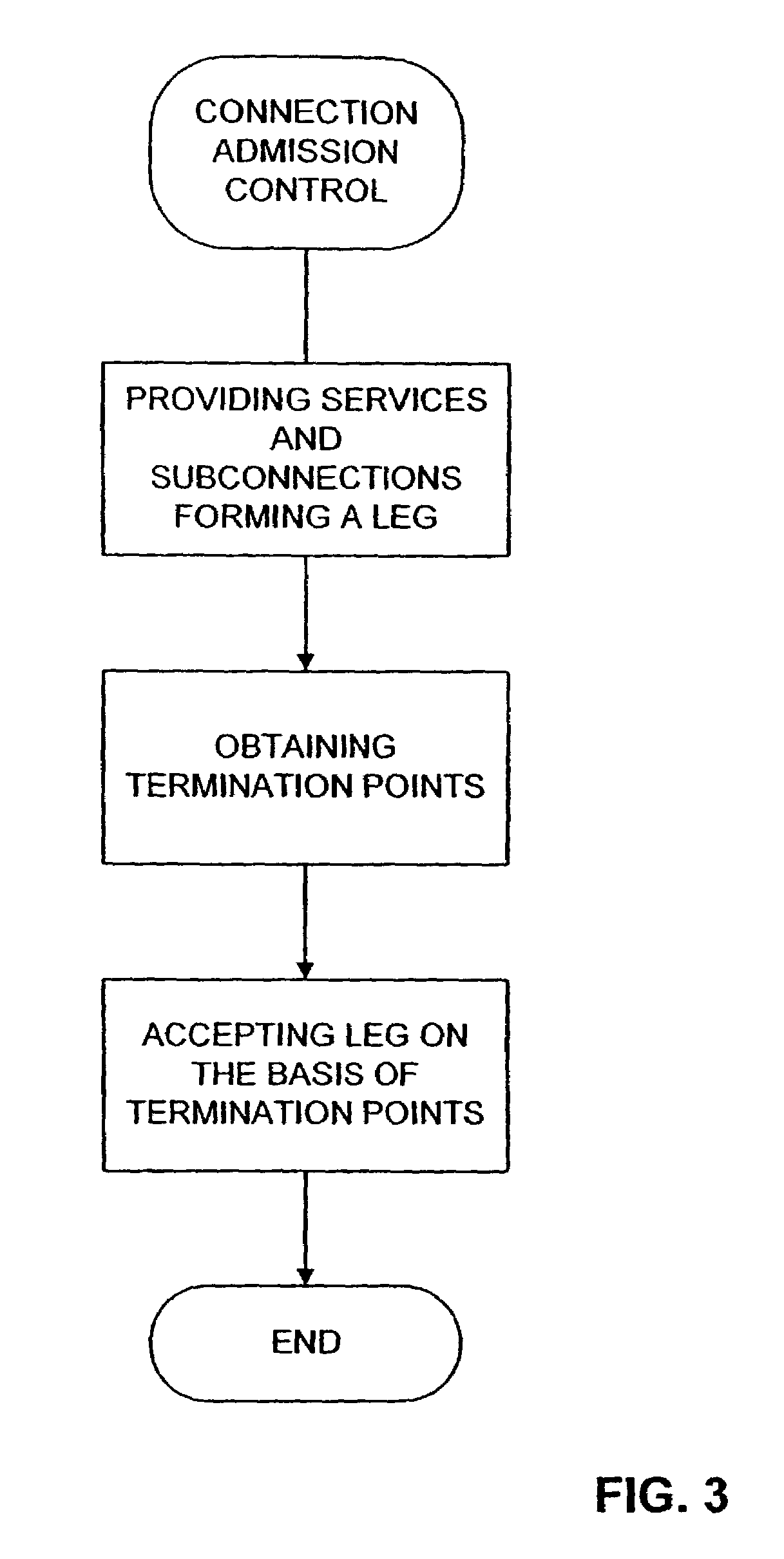
[0019]The idea of the present invention is to provide connection admission control for a whole leg of a through switch connection in an ATM switch.

[0020]In the following, a preferred embodiment of the present invention will be described by referring to FIGS. 2 to 4.

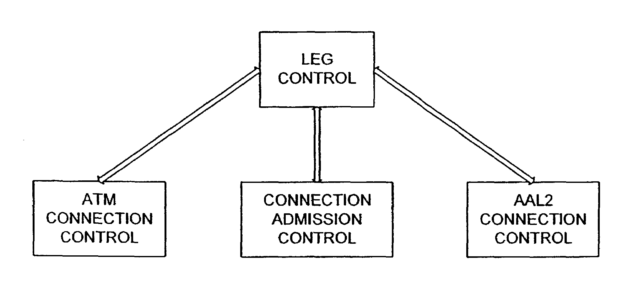
[0021]FIG. 2 shows a schematic block diagram of basic components of a switching apparatus like an ATM switch according to the present invention. As shown in FIG. 2, the ATM switch comprises a leg control, a connection control formed of an ATM connection control and an AAL2 connection control and a connection admission control. The ATM switch connects physical endpoints via a through switch connection. The through switch connection is composed of services and subconnections between the services. In the ATM switch, the leg control forms a leg being terminated by termination points and comprising specific services. The connection control provides the specific services and subconnections between the specific services which fo...


PUM


Abstract

A switching method and a switching apparatus in a telecommunication network for connecting physical endpoints via a through switch connection, wherein the through switch connection is composed of legs and a leg connector, and a leg is composed of services and subconnections between the services. A leg being terminated by termination points and comprising specific services is formed by leg control means, and the specific services and subconnections between the specific services which form the leg are provided by connection control means, the services being terminated by termination points. Further, connection admission control means accept connections being part of the through switch connection.

Description

CROSS-REFERENCE TO RELATED APPLICATION[0001]This application is a continuation of International Application PCT / EP99 / 10027 having an international filing date of Dec. 16, 1999 and from which priority is claimed under all applicable sections of Title 35 of the United States Code including, but not limited to, Sections 120, 363 and 365(c).FIELD OF THE INVENTION[0002]The present invention relates to a switching apparatus and method in a telecommunication network for connecting physical endpoints via a through switch connection. In particular, the present invention relates to the cooperation between leg control, connection control, connection admission control and hardware for providing connection admission control for ATM adaptation layer 2 connections in an Asynchronous Transfer Mode (ATM) network element.BACKGROUND OF THE INVENTION[0003]A through switch connection in an ATM network element or ATM switch in a telecommunication network is composed of legs and a leg connector. The throu...

Claims


Application Information

Patent Timeline
IPC IPC(8): H04L12/28H04L49/111H04Q11/04
CPCH04L49/3081H04Q11/0478H04L2012/5629H04L2012/5656
Inventor KINNUNEN, MATTIHIETANEN, KRISTIINAHOLMA, MAUNUAHOLA, HEIKKI
Owner NOKIA SOLUTIONS & NETWORKS OY
Learn More