
Refrigerator and airflow passage for ice making compartment of the same

a technology of ice making compartment and airflow passage, which is applied in the field of refrigeration, can solve the problems of increasing leakage and decreasing the efficiency of the ice making compartment, and achieve the effects of increasing the efficiency of the refrigerator, preventing leakage of cooling air, and increasing the amount of cooling air

Active Publication Date: 2007-09-25
LG ELECTRONICS INC
View PDF10 Cites 35 Cited by
  • Summary
  • Abstract
  • Description
  • Claims
  • Application Information

AI Technical Summary

Benefits of technology

The present invention is about a refrigerator with an improved ice making compartment. The invention includes an airflow passage that selectively opens and closes based on the movement of the refrigeration chamber door. This airflow passage allows for more efficient cooling air to be supplied to the ice making compartment without allowing foreign substances to enter. The invention also includes a duct and a cooling air passage formed at the outer surface of the ice making compartment to connect the duct with the ice making compartment. This airflow passage is selectively opened and closed based on the movement of the refrigeration chamber door, which increases the amount of cooling air supplied to the ice making compartment without allowing cooling air leakage. The invention also includes a restoring member and a protrusion to push the switching unit and ensure the cooling air passage is opened when the door is closed. Overall, the invention improves the efficiency and quality of the ice produced in the refrigerator.

Problems solved by technology

Further, although the supply of cooling air to the ice making compartment can be increased by increasing the size of the cooling air inlet hole, such an arrangement causes increased leakage of the cooling air when the refrigeration chamber door is opened, thereby decreasing the efficiency of the ice making compartment.

Method used


Image

  • Refrigerator and airflow passage for ice making compartment of the same
  • Refrigerator and airflow passage for ice making compartment of the same
  • Refrigerator and airflow passage for ice making compartment of the same

Examples


Embodiment Construction

[0042]Reference will now be made in detail to the preferred embodiments of the present invention, examples of which are illustrated in the accompanying drawings. Wherever possible, the same reference numbers will be used throughout the drawings to refer to the same or like parts.

[0043]Though a bottom freezer type refrigerator, in which a refrigeration chamber is located above a freezing chamber, is illustrated to describe the present invention, the present invention can be applied to various types of refrigerators as described previously. The present invention may be more effectively applied to a bottom freezer type refrigerator that has a large refrigeration chamber at an upper portion. Hereinafter, the term “refrigerator” will be used to denote a bottom freezer type refrigerator.

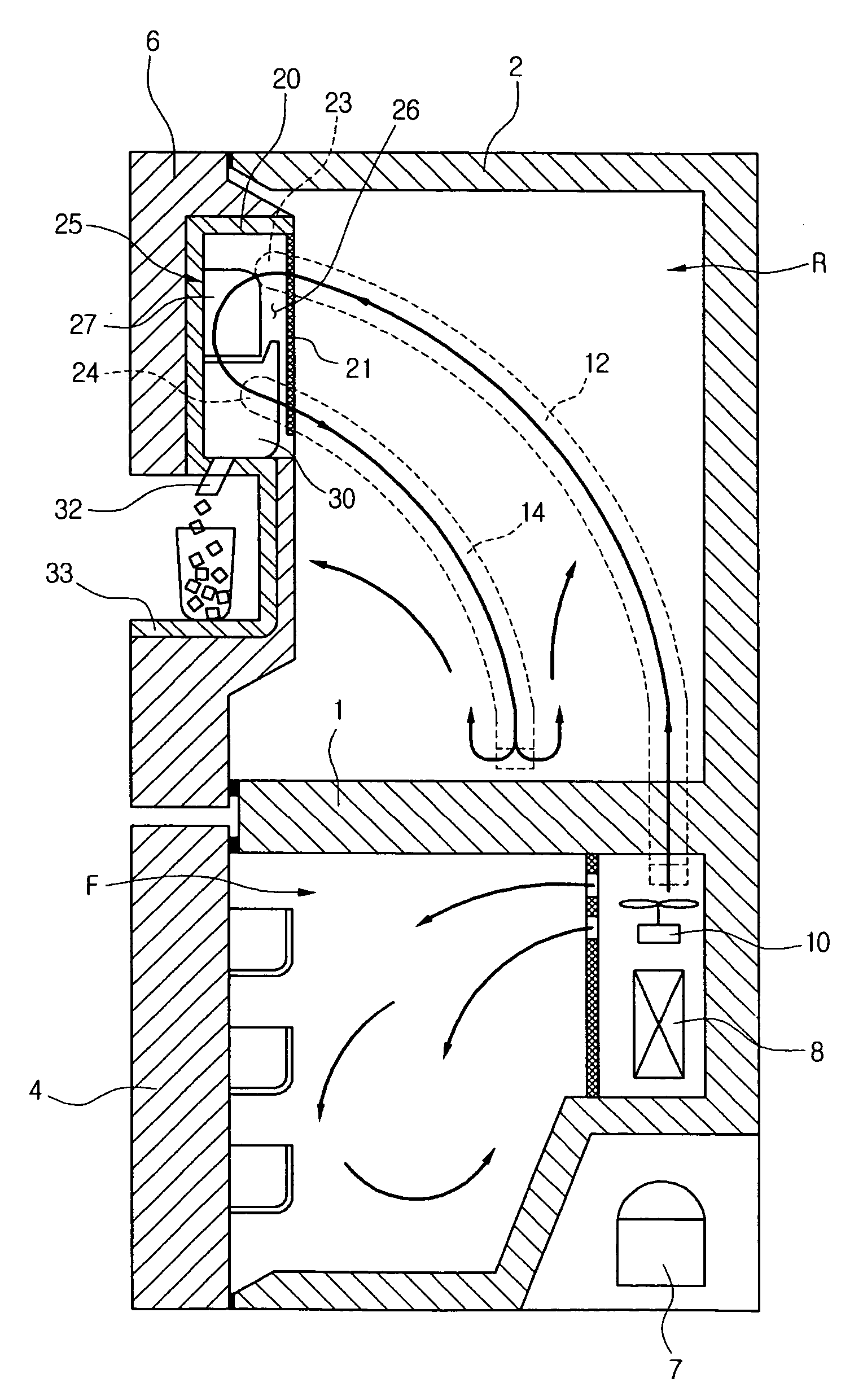
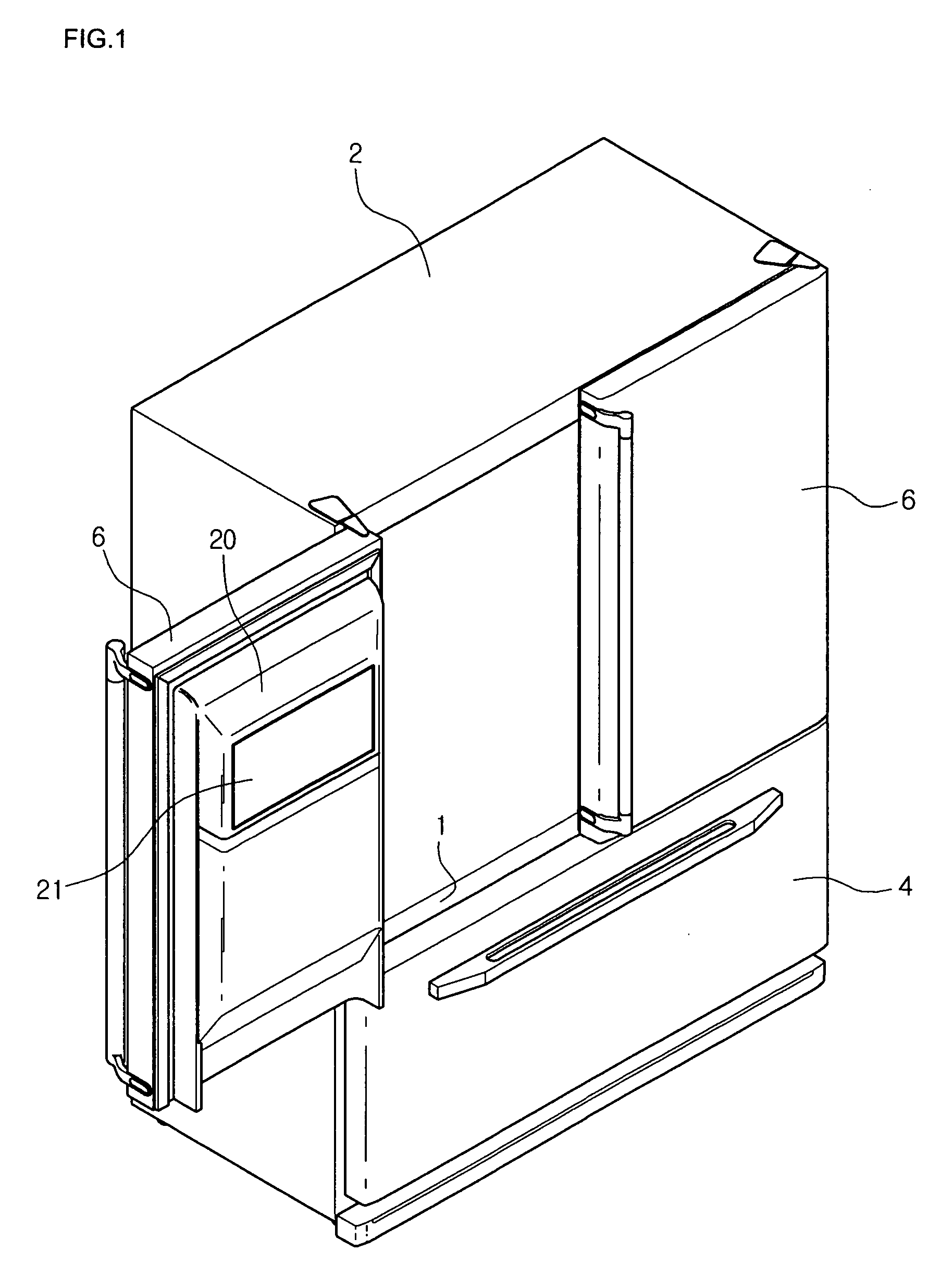
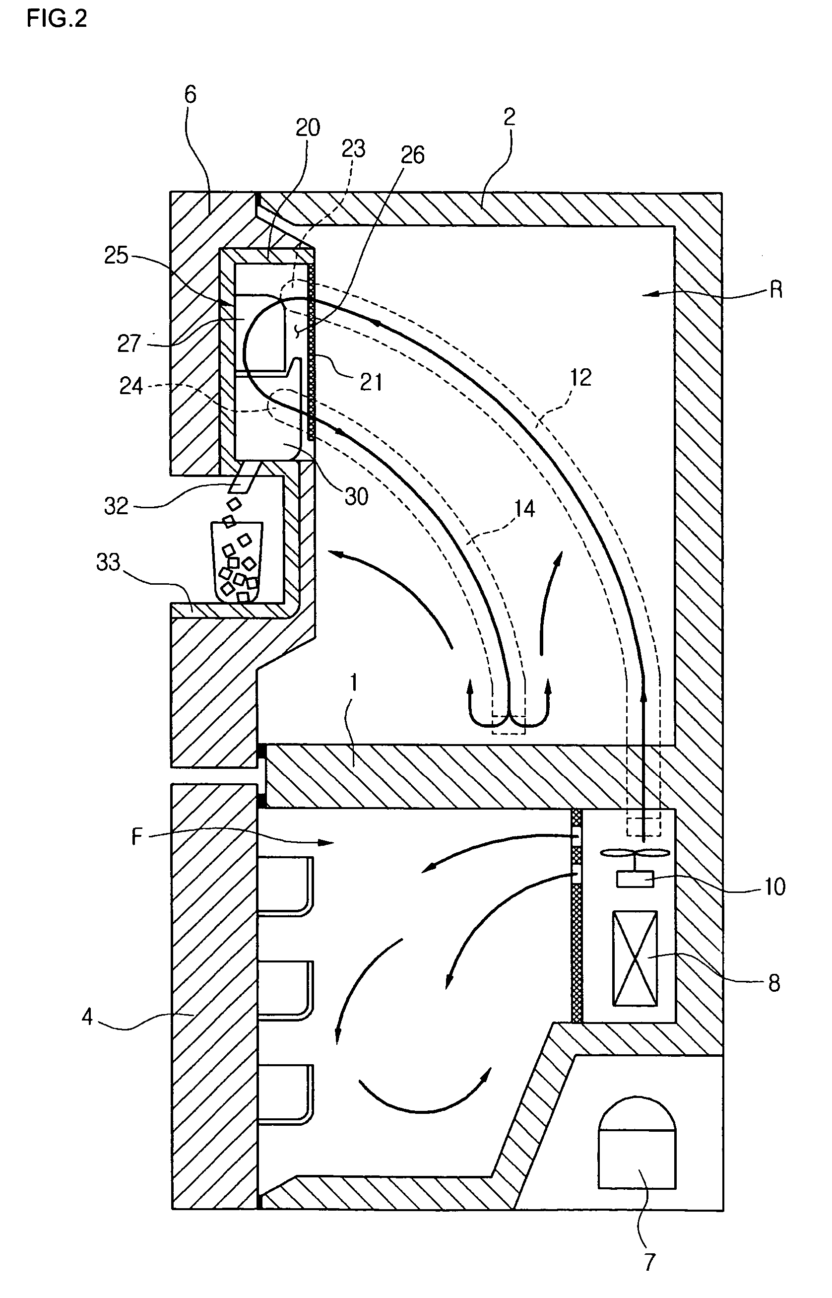
[0044]Referring to FIGS. 1 and 2, a refrigerator includes a main body 2 in which a refrigeration chamber (R) and a freezing chamber (F) are partitioned on above the other by a barrier 1, a refrigeration ch...


PUM

PropertyMeasurementUnit
temperatureaaaaaaaaaa
flexibleaaaaaaaaaa
external forceaaaaaaaaaa

Abstract

A refrigerator is provided with an airflow passage for an ice making compartment of the refrigerator. In the refrigerator, a main body has an opened side, and a door selectively closes the opened side of the main body. An ice making compartment is formed in the door, the ice making compartment being insulated from the outside and being kept at a low temperature. A duct is formed in the main body for exchanging cooling air with the ice making compartment, and a cooling air passage is formed at an outer surface of the ice making compartment to connect the duct with the ice making compartment. A switching unit closes the cooling air passage when the door is opened, and opens the cooling air passage when the door is closed. With this arrangement, the cooling air can be sufficiently supplied to the ice making compartment without the penetration of foreign substance.

Description

[0001]This application claims priority under 35 U.S.C. § 119(a) on Patent Application No. 10-2004-0034874 filed in Korea on May 17, 2004, which is herein incorporated by reference.BACKGROUND OF THE INVENTION[0002]1. Field of the Invention[0003]The present invention relates to a refrigerator, and more particularly, to a refrigerator and airflow passage for an ice making compartment of the refrigerator, in which a cooling air passage of the ice making compartment is associated with the opening and closing operations of a chilling compartment door to reduce the penetration of foreign substances and airflow loss. In the refrigerator and airflow passage of the present invention, the cooling air passage between the ice making compartment formed in the chilling compartment door and a refrigerator body is selectively opened and closed according to the closing and opening of the chilling compartment door to reduce the penetration of foreign substances and leakage of cooling air, while supply...

Claims


Application Information

Patent Timeline
Patent Type & Authority Patents(United States)
IPC IPC(8): F25C1/00F25C5/00F25D17/08F25D17/04F25D17/06F25D23/04F25D23/12
CPCF25D17/065F25D23/04F25C1/00F25C5/005F25C2400/10F25D17/045F25D23/12F25D2317/062F25D2317/0664F25D2317/0671F25D2317/0672F25D2400/04F25C5/22E06B7/2312E06B3/365E06B7/36E06B3/02E05Y2800/12E05Y2800/41
Inventor LEE, MYUNG RYULCHUNG, SUNG HOONKIM, SEONG JAESEO, CHANG HO
Owner LG ELECTRONICS INC
Learn More