Tire inflation system apparatus and method

a technology of tire inflation and tire pressure, which is applied in the direction of tire measurement, vehicle components, transportation and packaging, etc., can solve the problems of difficult manual check and maintain the optimum tire pressure for each and every tire, tire pressure might not be checked, and air may leakage from a tire, etc., to improve the ability to accurately check and monitor the inflation pressure of a vehicle tire.

Active Publication Date: 2007-09-25
HENDRICKSON USA L L C
View PDF52 Cites 91 Cited by
  • Summary
  • Abstract
  • Description
  • Claims
  • Application Information

AI Technical Summary

Benefits of technology

[0014]One objective of the present invention is to provide a tire inflation system with an improved ability to accurately check and monitor the inflation pressure of a vehicle tire.
[0015]Another objective of the present invention is to provide a tire inflation system that inflates a vehicle tire with improved control, thereby providing relatively rapid inflation without substantial over-inflation of the tire.

Problems solved by technology

However, it is well known that air may leak from a tire, usually in a gradual manner, but sometimes rapidly if there is a problem with the tire, such as a defect or a puncture caused by a road hazard.
The large number of tires on any given trailer setup makes it difficult to manually check and maintain the optimum tire pressure for each and every tire.
This difficulty is compounded by the fact that multiple trailers in a fleet may be located at a site for an extended period of time, during which the tire pressure might not be checked.
Such operation may increase the chance of failure of a tire in service as compared to operation with tires in an optimum inflation range.
Moreover, should a tire develop a leak, for example, as a result of striking a road hazard, the tire could fail if the leak continues unabated as the vehicle travels over-the-road.
The potential for tire failure often is more pronounced in vehicles such as tractor-trailers that travel for long distances and / or extended periods of time.
However, these prior art systems exhibit several disadvantages.
However, such systems generally also can give false positive warnings.
For example, simply filling the air lines may cause a sensor to give a false positive warning.
Moreover, constantly pressurized rotary unions have high contact pressure at the sealing point of the rotary union seals, which limits the useful life of the rotary union.
However, access to PC's, the proper interface cables and interface modules often are not readily available in the field, creating problems when the tire pressure setting is to be changed.
However, such systems require each tire on a given trailer to be manually inflated, which is problematic since many original equipment manufacturers of trailers do not have consistent shop air pressure to enable uniform tire inflation, particularly on higher-inflation pressure tires.
Consequently, the self-learn mode sets to the lowest tire pressure, which can be significantly less than optimal.
However, if the control systems of the prior art tire inflation systems detect a failure or malfunction of a check valve, they do not compensate by maintaining pressure in the delivery lines, thereby allowing a tire to deflate should a respective check valve malfunction.
These prior art rotary unions also have a means of attachment to the axle that is not optimum for long-term use and hose barb fittings that potentially can allow air hoses to work loose over time.
With such characteristics, these prior art rotary unions thus are potentially susceptible to premature failure, which is highly undesirable.
As a result, the tire inflation systems of the prior art include significant disadvantages by not providing reliable automatic control over the inflation process, failing to keep the system pressurized in the event of malfunction of check valve, failing to communicate system problems, and potentially lacking long-term rotary union stability.

Method used


Image

  • Tire inflation system apparatus and method
  • Tire inflation system apparatus and method
  • Tire inflation system apparatus and method

Examples


Embodiment Construction

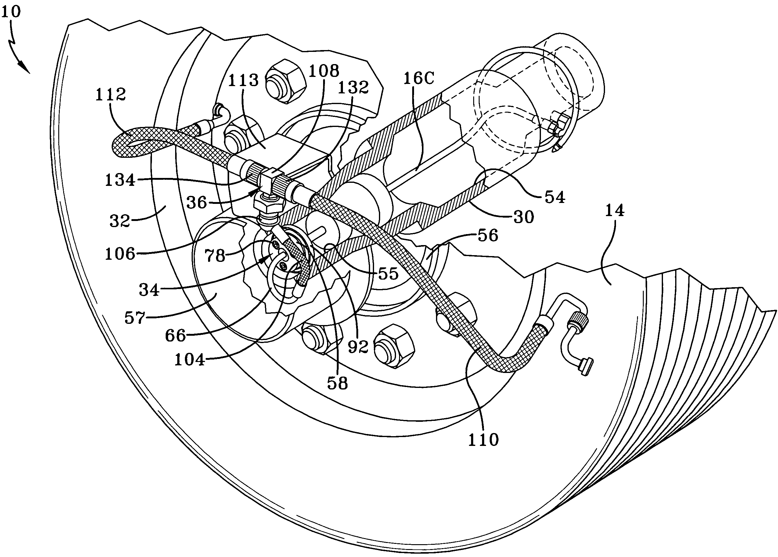
[0043]The present invention utilizes a tire inflation system of the intermittent type, but with a simple controller that is free of the self-learn or PC interface systems found in prior art systems that are described above. The components of the system of the present invention and the method of control of those components provide more reliable control than systems of the prior art, communication of system problems, and the ability to maintain pressure should a check valve fail. In addition, the rotary union of the system includes several aspects that make it more dependable and likely longer-lived than rotary unions of the prior art. It is to be understood that the drawings and the following description are for purposes of illustrating a preferred embodiment of the invention and not for limiting the same.

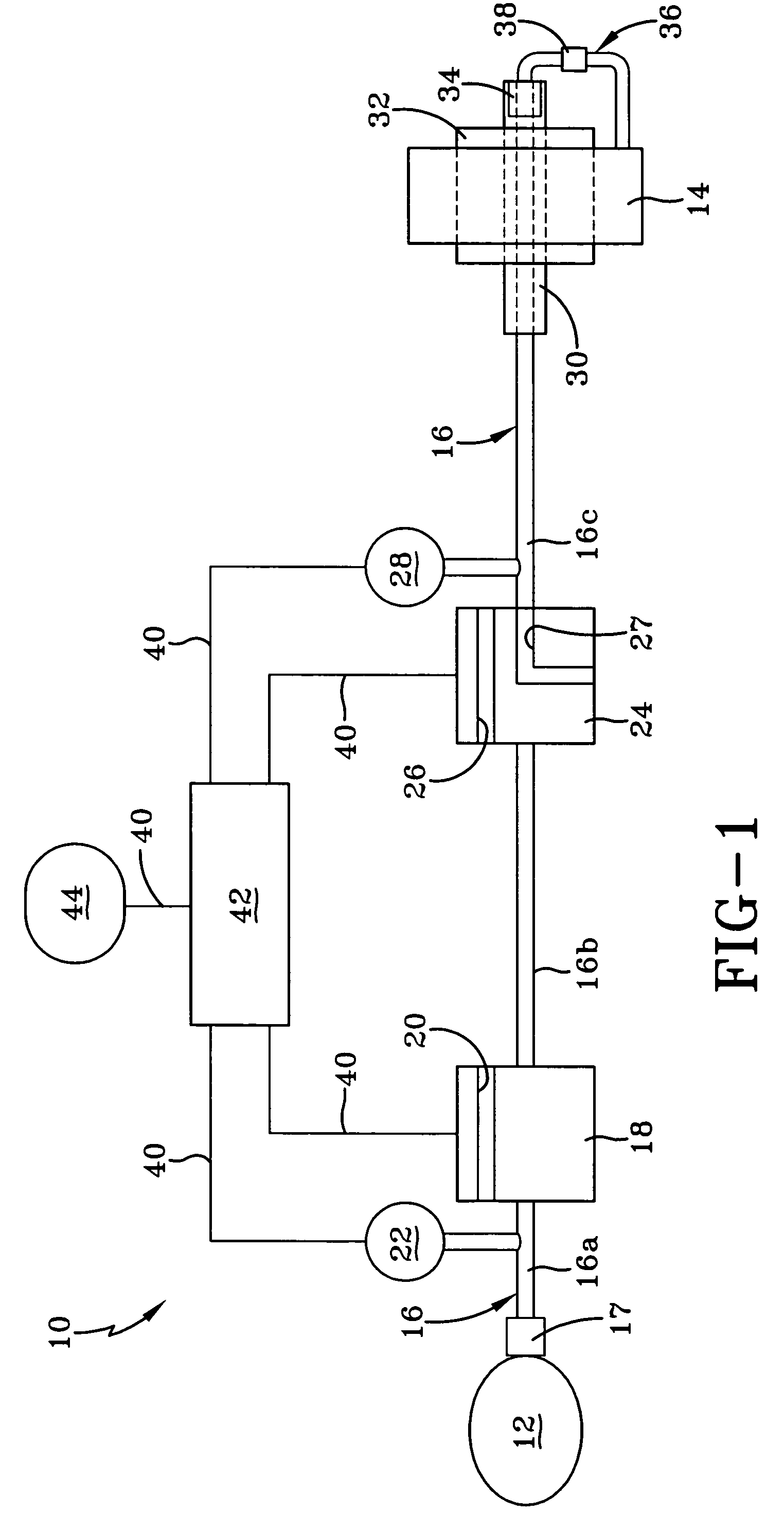
[0044]Turning now to FIG. 1, a tire inflation system of the present invention is indicated generally at 10 and is schematically shown. Tire inflation system 10 is a pneumatic system...


PUM


Abstract

A tire inflation system includes an air supply source in selective fluid communication with a tire via a pneumatic conduit. A method of inflating the system includes providing a tire pressure retention valve in the pneumatic conduit adjacent to the tire. An inflation pressure of the tire is determined with a step-up procedure, in which air bursts are communicated from the air supply source to a portion of the pneumatic conduit between the air supply source and the tire pressure retention valve. The volume of at least one selected communicated air burst is related to a volume of a section of the conduit. The tire is inflated with an extended-pulse procedure, in which extended bursts of air are communicated from the air supply source to the tire. A shut-down sequence is performed once a predetermined target inflation pressure in the tire is reached.

Description

CROSS-REFERENCE TO RELATED APPLICATIONS[0001]This application is a continuation-in-part of U.S. patent application Ser. No. 10 / 794,942, filed on Mar. 5, 2004 now abandoned.BACKGROUND OF THE INVENTION[0002]1. Field of the Invention[0003]The invention relates to the art of tire inflation systems. More particularly, the invention relates to tire inflation systems for heavy-duty vehicles such as tractor-trailers or semi-trailers, which can operate as the vehicles are moving.[0004]2. Background Art[0005]All tractor-trailers include at least one trailer, and sometimes two or three trailers, all of which are pulled by a single tractor. Each trailer typically includes eight or more tires, each of which is inflated with air. Optimally, each tire is inflated to a recommended pressure that is usually between about 70 pounds per square inch (psi) and about 130 psi. However, it is well known that air may leak from a tire, usually in a gradual manner, but sometimes rapidly if there is a problem w...

Claims


Application Information

Patent Timeline
Patent Type & Authority Patents(United States)
IPC IPC(8): B60C29/00B60C23/02B60C23/00
CPCB60C23/003B60C23/00318B60C23/00336B60C23/00345B60C23/00354B60C23/00363B60C23/00372
Inventor WHITE, JAY D.STEINER, RICHARD R.CERVANTEZ, JESSE W.
Owner HENDRICKSON USA L L C
Why Eureka
Try Eureka