Panel display driving device and driving method

Active Publication Date: 2007-09-25
PIONEER CORP
View PDF23 Cites 279 Cited by
  • Summary
  • Abstract
  • Description
  • Claims
  • Application Information

AI Technical Summary

Problems solved by technology

Therefore, when the display panel 10 is driven for a prolonged time, the resistance value of the EL elements becomes non-uniform, causing a variance in light-emission luminance which results in problems such as an irregular luminance across the screen and screen burning.

Method used


Image

  • Panel display driving device and driving method
  • Panel display driving device and driving method
  • Panel display driving device and driving method

Examples


Embodiment Construction

[0068]Preferred embodiments of the present invention will now be described in detail with reference to the accompanying drawings.

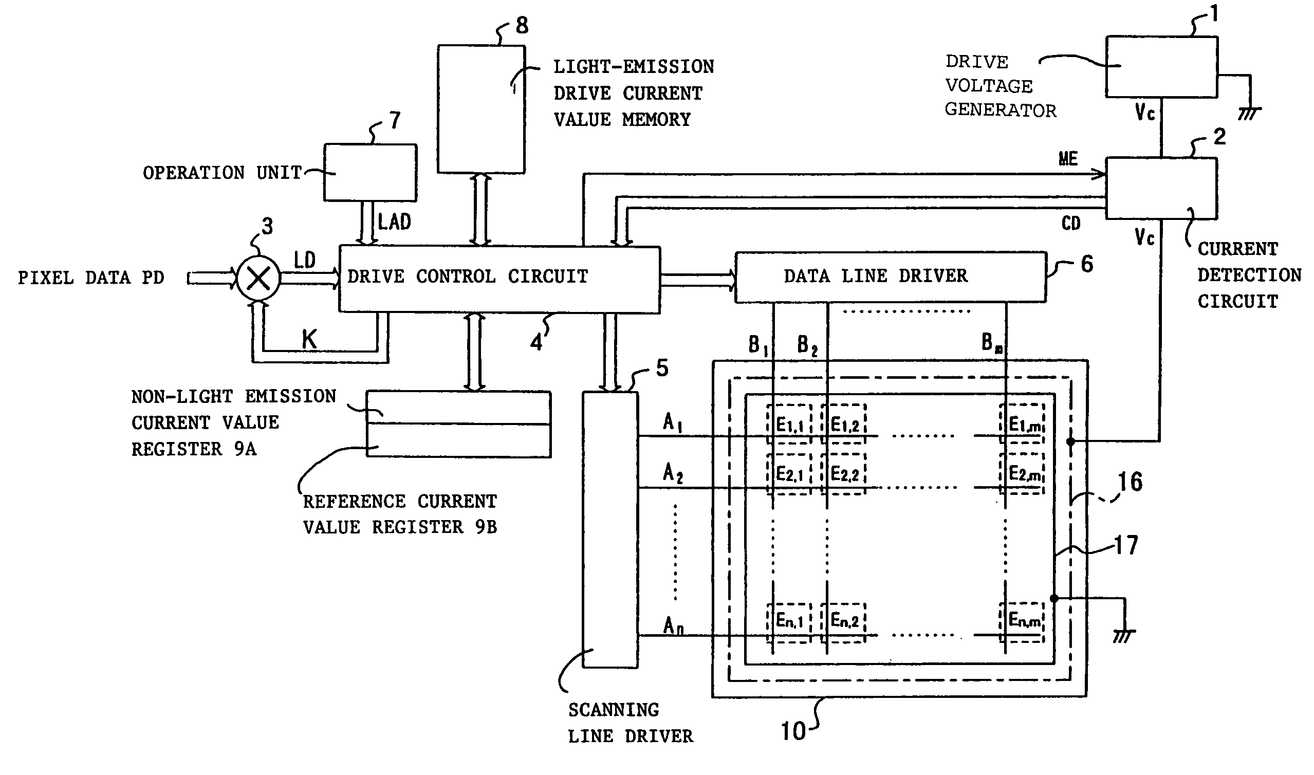
[0069]FIG. 3 is a schematic diagram showing the structure of an embodiment of an electroluminiscent active matrix drive type EL display device according to the present invention (henceforth referred to as EL display device)

[0070]As shown in FIG. 3, this EL display device comprises a drive voltage generator circuit 1, a current detection circuit 2, a multiplier 3, a drive control circuit 4, a scanning line driver 5, a data line driver 6, an operation unit 7, a light-emission drive current memory 8, a non-light emission current value register 9A, a reference current value register 9B and a display panel 10.

[0071]The display panel 10 is formed by an anode power line 16, a cathode power line 17, 1 screen having n horizontal scanning lines A1 to An, and m data lines B1 to Bm arranged in such a manner that they intersect each other. Also, a drive voltage Vc is a...


PUM


Abstract

A display panel driving device and driving method for providing high quality images without irregular luminance even after long-time use. The value of the light-emission drive current flowing when causing each light-emission elements bearing each pixel to independently emit light in succession is measured, then the luminance is corrected for each input pixel data based on the above light-emission drive current values, associated with the pixels corresponding to the input pixel data. According to another aspect, the voltage value of the drive voltage is adjusted in such a manner that one value among each measured light-emission drive current value becomes equal to a predetermined reference current value. According to a further aspect, the current value is measured while an off-set current component corresponding to a leak current of the display panel is added to the current outputted from the drive voltage generator circuit and the resultant current is supplied to each of the pixel portions.

Description

BACKGROUND OF THE INVENTION[0001]1. Field of the Invention[0002]The present invention relates to an active matrix-type display panel driving device and a driving method for same.[0003]2. Description of the Related Art[0004]In recent years, electroluminiscent display devices (henceforth referred to as EL display devices) incorporating a display panel using organic electroluminiscent elements (henceforth referred to as EL elements) as light-emission elements carrying pixels have drawn considerable attention. Driving methods for panel displays using those EL display devices known in the prior art include simple matrix drives and active matrix drives. EL display devices with active matrix drives are advantageous in that they consume less power than simple matrix types, and have a smaller cross-talk between pixels, being especially appropriate for large-screen or high resolution displays.[0005]FIG. 1 is a diagram showing the basic structure of an active matrix drive type EL display devic...

Claims


Application Information

Patent Timeline
IPC IPC(8): G09G5/00G09G3/20G09G3/32
CPCG09G3/3233G09G3/2011G09G3/2022G09G2310/0221G09G2320/0693G09G2320/0233G09G2320/0285G09G2320/029G09G2320/043G09G2310/04
Inventor ISHIZUKA, SHINICHITSUCHIDA, MASAMIOCHI, HIDEOSAKAMOTO, TSUYOSHI
Owner PIONEER CORP
Why Eureka
Try Eureka