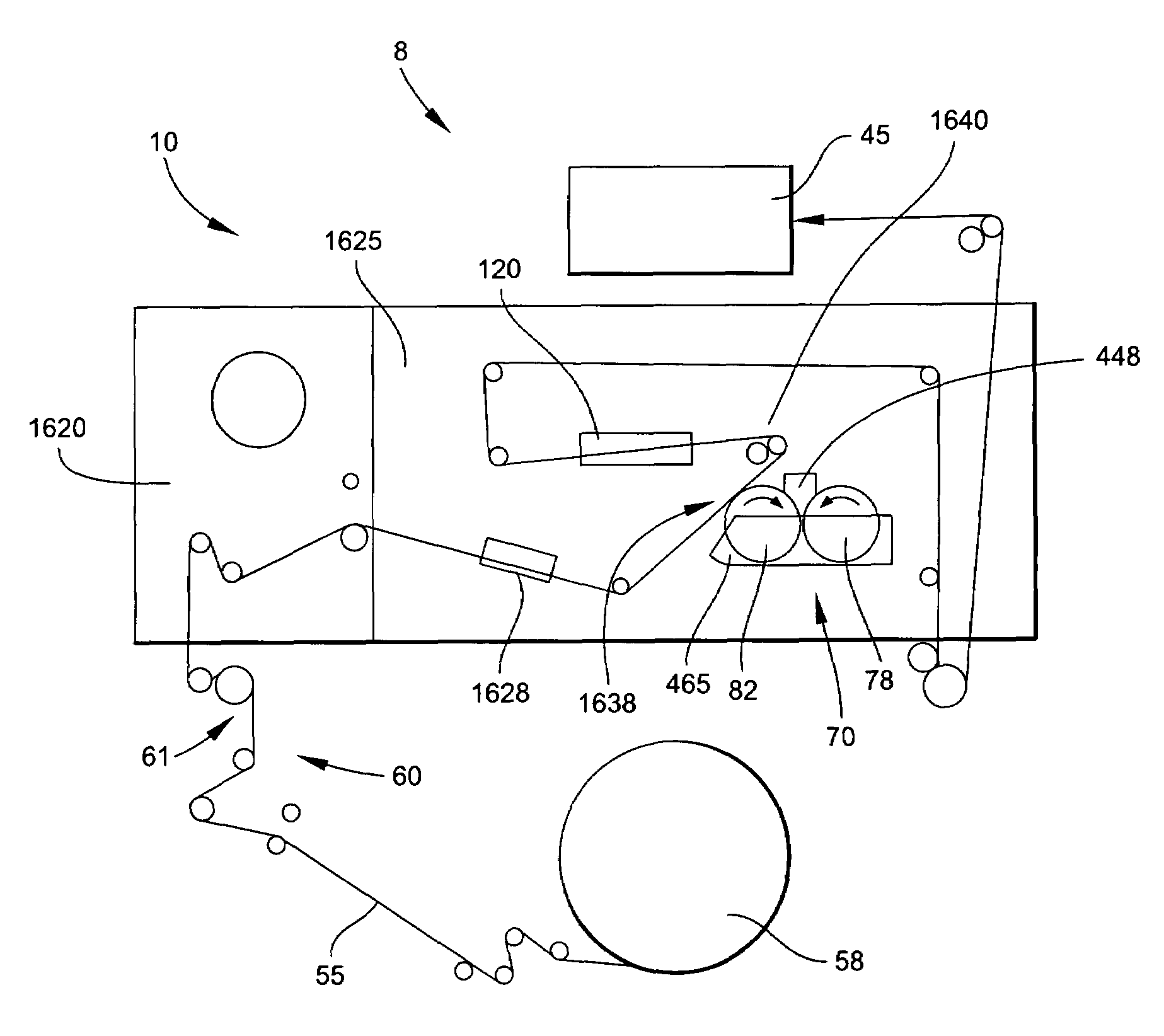
[0013]In one aspect, the present invention relates to equipment and methods for applying an additive material to a substrate, such as a paper web used as a wrapping material for cigarette manufacture. Those equipment and methods are particularly suitable in connection with the operation of an automated cigarette making machine, and for the purpose of applying a predetermined pattern of additive material to a continuous strip of paper web. An additive application apparatus includes a first roller adapted to receive the additive material (e.g., a
coating formulation in liquid form) and a second roller adjacent to the first roller adapted to transfer the additive material from the first roller to the substrate (e.g., paper web). That apparatus also includes an additive material reservoir adjacent to the first roller for containing the additive material, and for supplying the additive material to the first roller. The additive material so supplied is positioned within pockets, grooves or indentations within the roll face of the first roller. For that apparatus, the roll face of the second roller is in roll contact with the roll face of the first roller in one location, and the roll face of the second roller is in contact with the paper web in another location; thus allowing for a predetermined transfer of additive material in a two-step manner. That is, when the additive material is supplied to pockets within the roll face of the first roller, that additive material is transferred to the roll face of the second roller; and when the second roller contacts the advancing paper web, the additive material is transferred from the roll face of the second roller and applied to the advancing paper web.
[0015]In another embodiment of an additive application apparatus, additive material (e.g., a
coating formulation in paste form) is applied to a substrate (e.g., a paper web) using a
system that employs a first roller adapted to (i) receive an additive material from an additive material reservoir, and (ii) apply that additive material to the substrate. Preferably, the first roller comprises a plurality of pockets, grooves or indentations that are aligned or arranged in the form of a pattern on the roll face of that roller. When the additive material is supplied to the first roller, a predetermined amount of the additive material is contained in each of the plurality of pockets. A second roller is in roll contact with the first roller, and the paper web passes through the location or region where those two rollers make roll contact. Such roll contact facilitates transfer of the additive material from the first roller to the paper web.
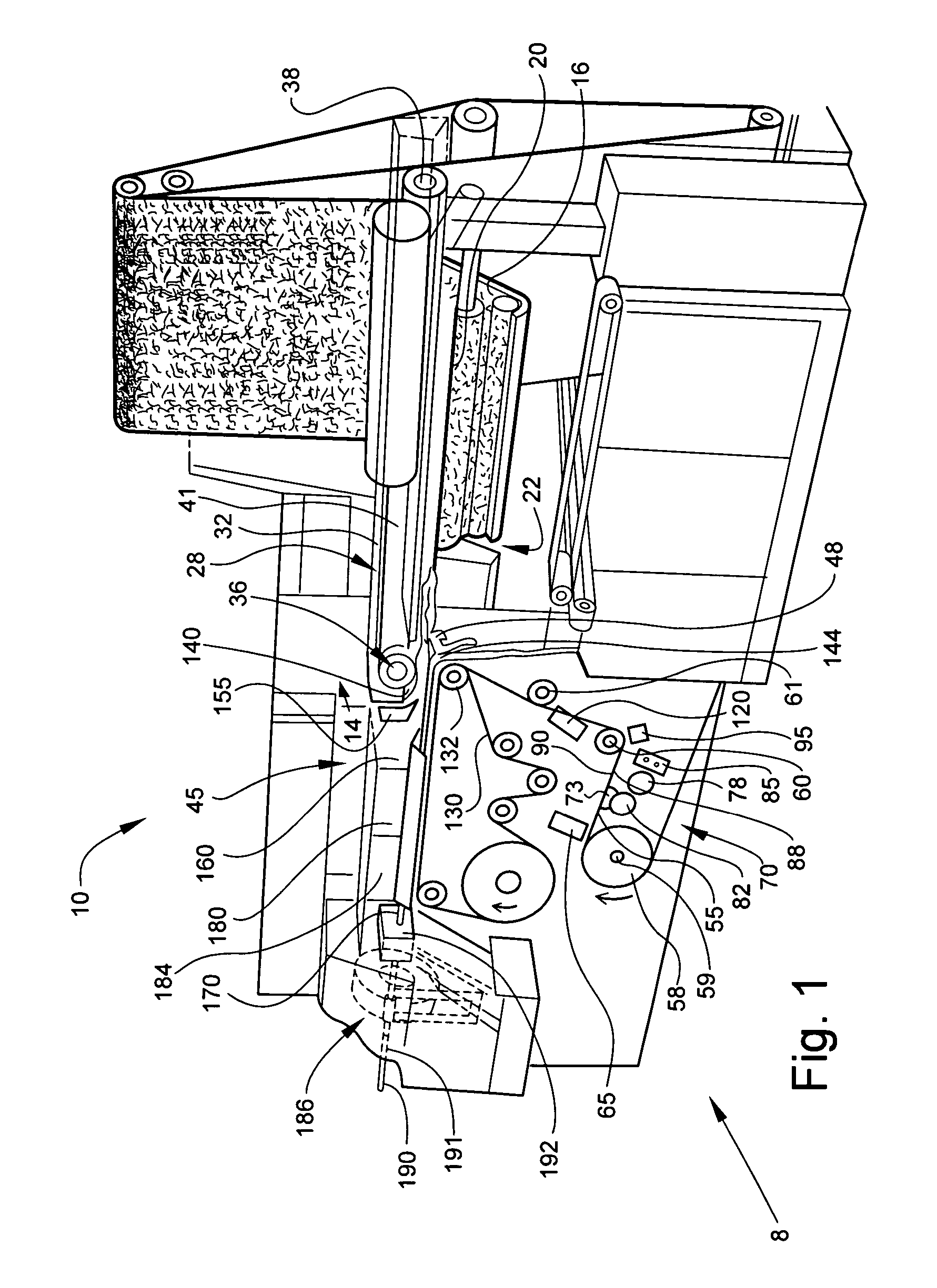
[0020]The present invention, in another aspect, relates to a
system useful for retaining on a paper web an additive material that has been applied to that paper web. The additive material can be a material that is applied to the paper web in a previous
processing step, such as using gravure printing techniques (e.g., using so-called “off-line” techniques), or while that paper web is being used for the manufacture of cigarettes within a cigarette making machine (e.g., using on-line techniques). The
system most preferably is located in the garniture entrance region of the cigarette making machine, and particularly in the finger rail region of the cigarette making machine. The system comprises a finger rail
assembly and a garniture entrance cone, which are located in a region of the cigarette making machine adapted to receive a continuous paper web. The paper web is advanced between the lower region of the finger rail
assembly and the upper region of the garniture entrance cone. The system includes at least one
air chamber (e.g., preferably each finger rail of the finger rail
assembly includes an
air chamber) located above the advancing paper web and a supply of pressurized or compressed gas (e.g., air) is fed into that
air chamber (e.g., a manifold or tubular channel). The air chamber includes a plurality of air distribution outlets or air passageways directed toward the lower surface of the system, and as such, air flows out of the air chamber. When a
high velocity stream of air exits the air distribution outlets and is directed generally downward, a zone of air turbulence preferably is created above the advancing paper web. That turbulence provides downward force that maintains the paper web a distance away from (e.g., spaced from) the finger rail assembly of the cigarette making machine. As a result, the additive material is retained on the paper web, and undesirable transfer of the additive material to the finger rail components of the cigarette making machine (and other regions of the cigarette making machine) is minimized, avoided or prevented.
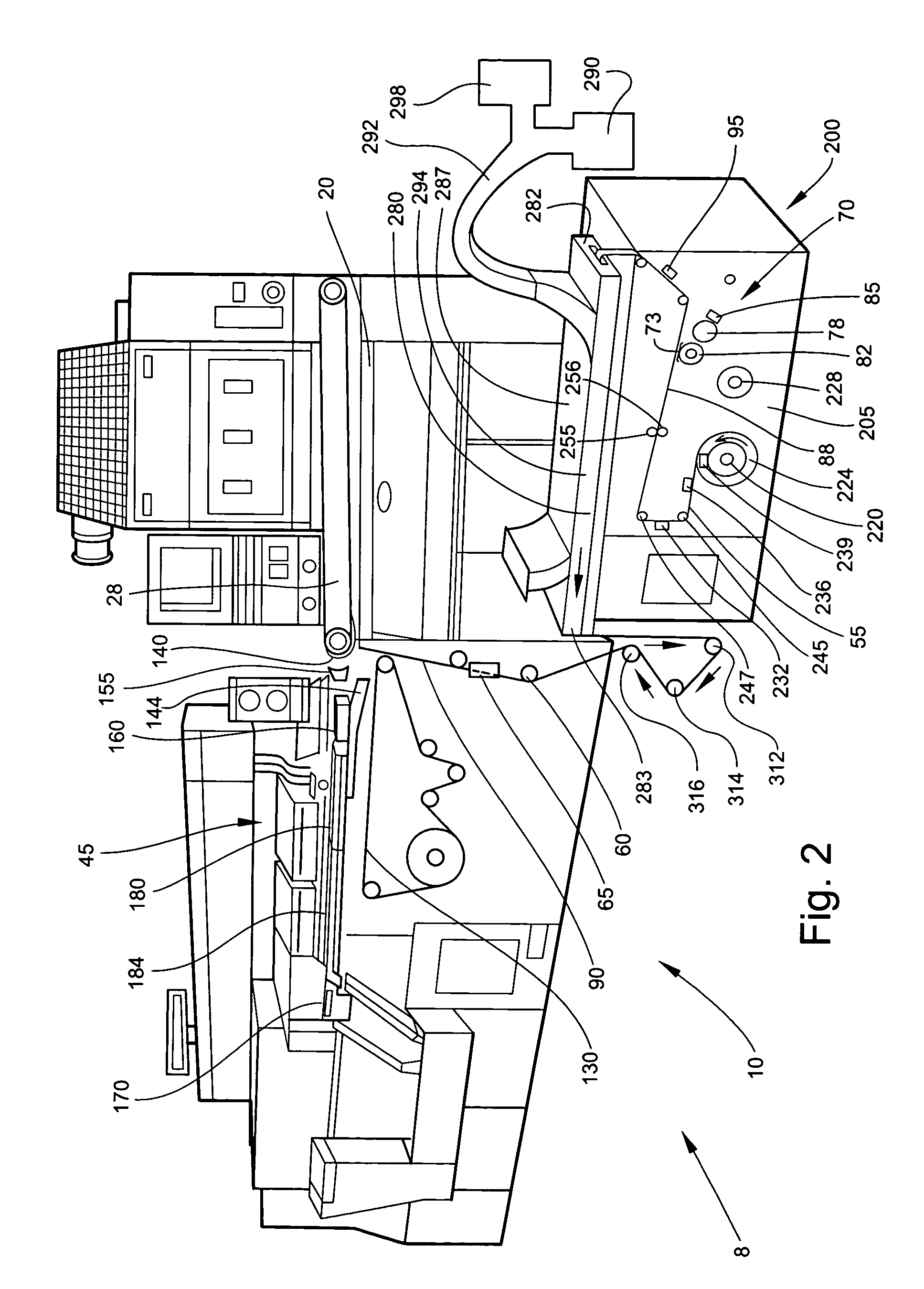
[0021]The present invention, in another aspect, relates to another system useful for retaining on a paper web an additive material that has been applied to that paper web. That system encompasses modification of a garniture entrance cone (which is designed to be positioned below the advancing paper web within a cigarette making machine). An entrance cone of one aspect of the present invention is adapted to possess an air chamber. That air chamber (e.g., manifold) is adapted to receive a flow or
stream of gas (e.g., air) from a supply of pressurized or
compressed air. Two air channels, both providing air outlets, or other suitably adapted air distribution means, are directed generally longitudinally, and are designed so as to provide a flow of air generally upwardly and generally outwardly. As a result, for each of opposing edges of the paper web (i.e., the right and left sides of the paper web relative to the longitudinal axis of that web) that pass over that entrance cone, the
stream of air exiting each channel creates a zone of low air pressure zone between that paper web and the upper surface of the entrance cone. Each of the paper web edges is affected by this low pressure zone, and each edge is urged toward the entrance cone and away from the finger rail components of the cigarette making machine (and other regions of the cigarette making machine). As a result, contact of the paper web and additive material with certain components of the cigarette making machine is minimized, avoided or prevented.
[0022]In one embodiment of the foregoing, an apparatus for the manufacture of cigarettes is adapted to minimize, avoid or prevent transfer of an additive material applied to a paper web from that paper web to surfaces of certain components of that apparatus. The apparatus includes a finger rail assembly comprising a pair of finger rails positioned at the distal, or exit, end of a suction rod
conveyor system. The apparatus also includes a garniture entrance cone positioned below the pair of finger rails, essentially as is conventional in a commercially available automated cigarette making machine. The pair of finger rails and the garniture entrance cone are adapted to receive between them a continuous strip of advancing paper web. In certain circumstances, the advancing paper web has a predetermined pattern of additive material (e.g., bands) applied thereto. Each finger rail includes an air chamber, and the air chamber is adapted to receive a
high velocity stream of air. Each air chamber has a plurality of air distribution outlets along its length directed generally downward toward the entrance cone. Those air distribution outlets can be arranged in either a random or a predetermined pattern, preferably so as to provide a turbulent flow of air below each finger rail. In the preferred embodiments, the stream air and the design of the air outlet pattern provides for a relatively consistent air flow from each of the various air distribution outlets. When the stream of air exits the air distribution outlets, a zone of
air movement (e.g., turbulence) is created above the advancing paper web; and the action of that
high velocity air flow acts to maintain the paper web a distance away from the finger rails. Preferably, the entrance cone comprises an air chamber, and high velocity or pressurized air is fed into that air chamber. Two air channels or slots, both providing air outlets, or other suitably adapted air distribution means, are directed generally longitudinally, and are designed so as to provide a flow of air generally upwardly and generally outwardly. When the high velocity air exits the slots of the entrance, a zone of low pressure is created between the paper web and the upper surface of the entrance cone. Each of the side edges of the paper web is affected by this low pressure zone, and is urged toward the entrance cone upper surface and away from the finger rails; and contact of the paper web with components of the finger rail assembly is minimized, avoided or prevented. Thus, an
improved method for the manufacture of smoking articles, such as cigarettes, is provided.

