Telescopically adjustable support brace

Inactive Publication Date: 2007-10-02
SHINAULT EDWIN K
View PDF25 Cites 47 Cited by
  • Summary
  • Abstract
  • Description
  • Claims
  • Application Information

AI Technical Summary

Benefits of technology

[0026]It is an advantage of the present invention to provide a brace that is easily disassembled after use, thereby permitting a user to remove excess concrete from the brace and prevent damage and/or f

Problems solved by technology

First, the process is very labor intensive and takes a great deal of time.
Second, the wood braces must be pulled out right before the concrete level reaches it, which is difficult to do, considering the r

Method used


Image

  • Telescopically adjustable support brace
  • Telescopically adjustable support brace
  • Telescopically adjustable support brace

Examples


Embodiment Construction

[0038]The best mode for carrying out the invention is presented in terms of its preferred embodiment, herein depicted within FIGS. 1 through 9.

1. DETAILED DESCRIPTION OF THE FIGURES

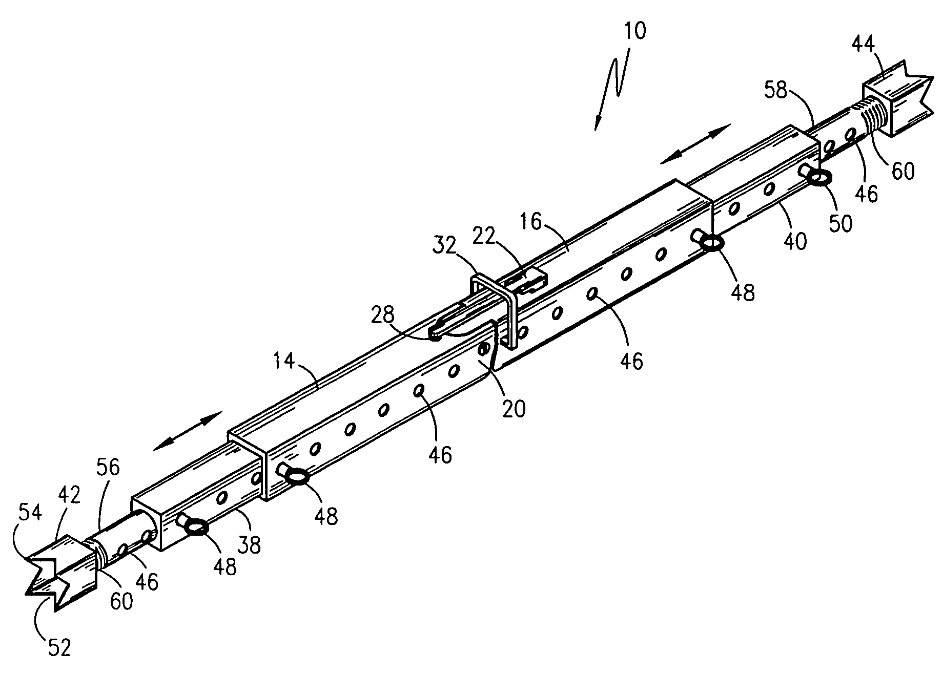
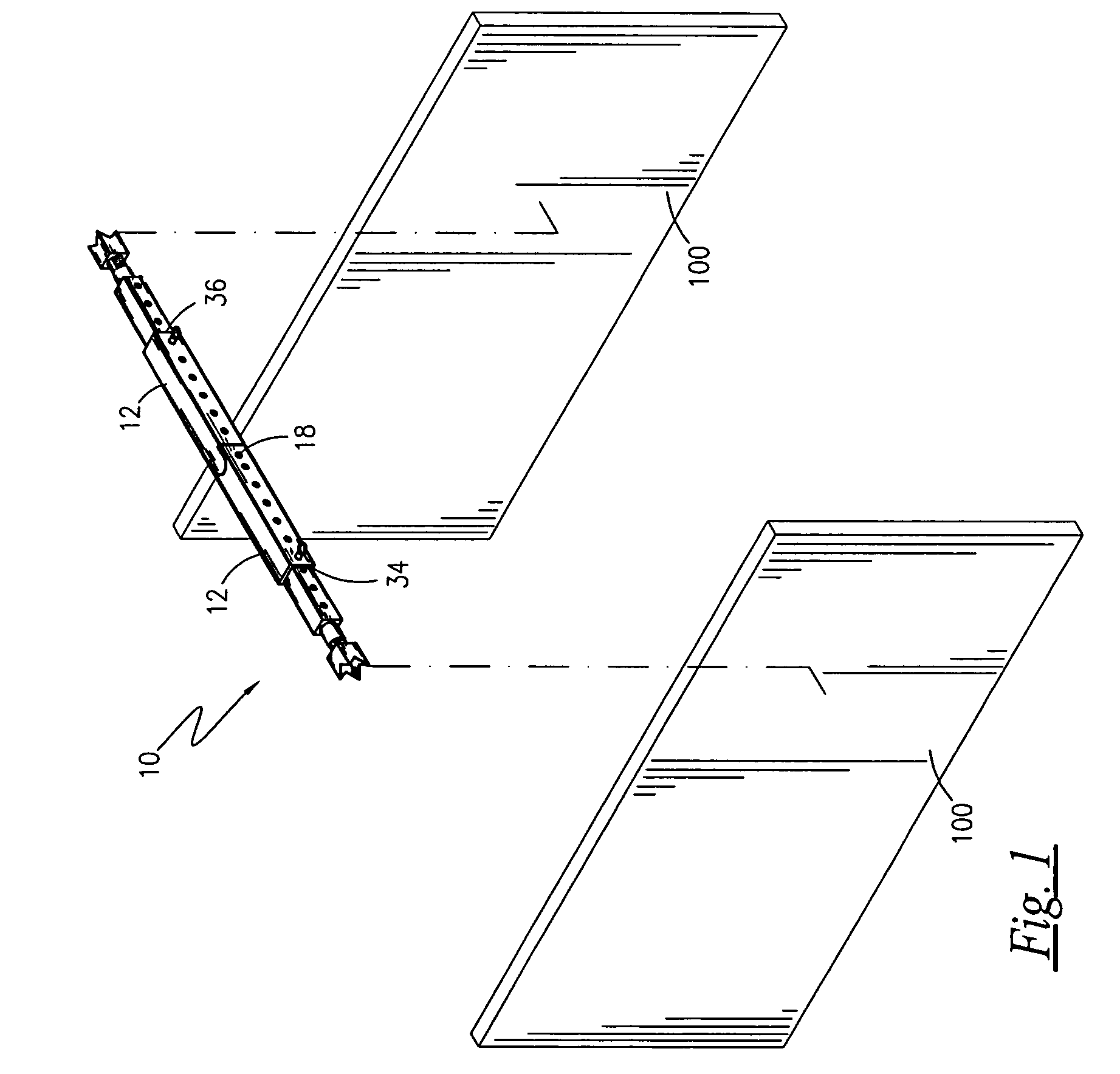
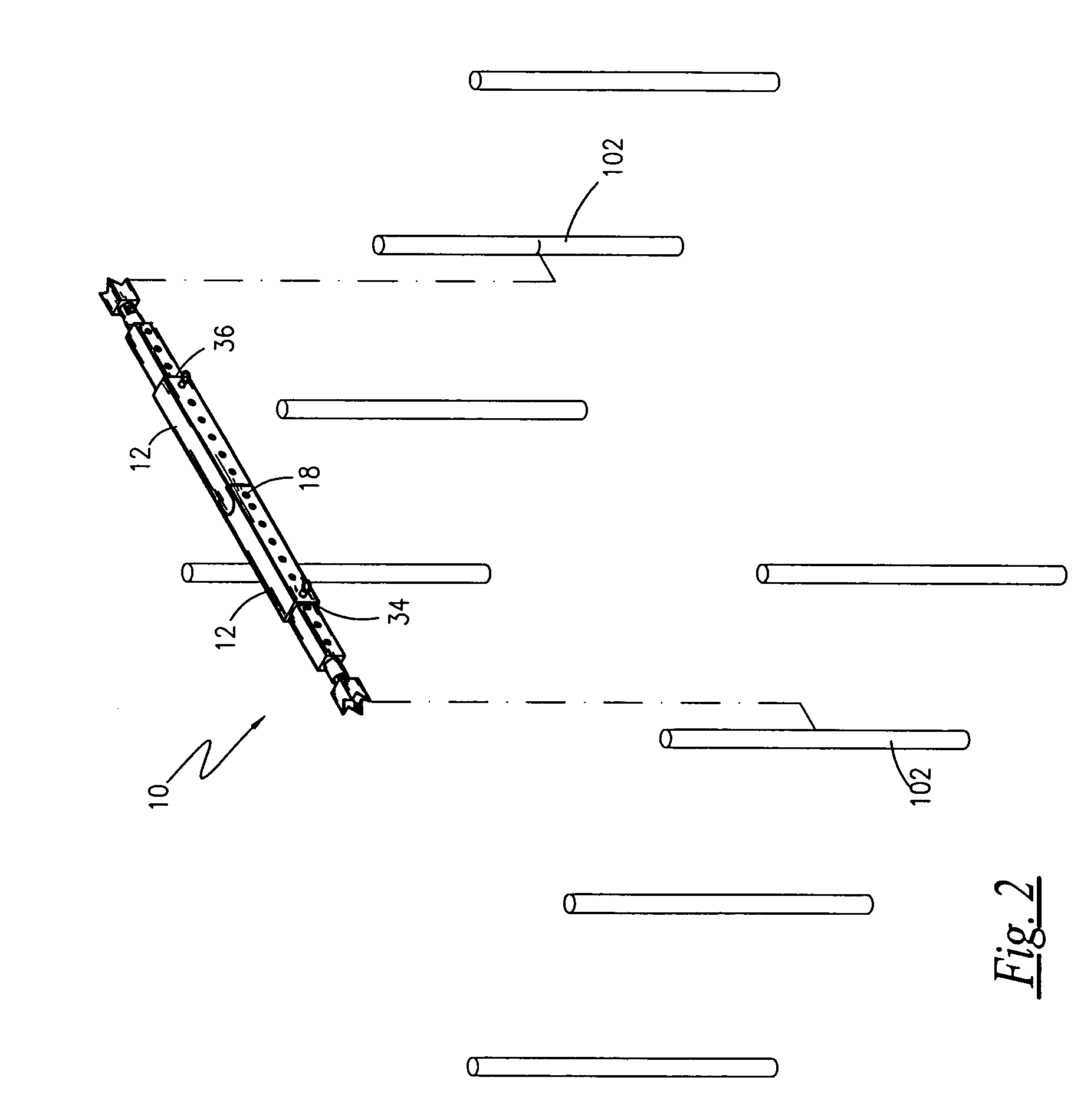
[0039]Referring now to FIG. 1 through FIG. 9, a telescopically adjustable support brace 10 (hereinafter “brace”) is shown in accordance with a preferred embodiment of the present invention. The brace 10 is envisioned for use in maintaining a specified linear distance or width between two objects, especially two objects that may tilt beyond a vertical or substantially vertical position. By way of example only, and not a limitation on the scope of the invention as claimed, in FIG. 1, the brace 10 is shown in supporting two wall forms 100 to prevent tilting of the wall forms 100 toward one another. In FIG. 2, the brace 10 is shown in supporting two upstanding reinforcement bars 102 (or re-bar as it is known in the trade). The brace 10 comprises a linearly elongated crossbar (generally denoted as 12) terminat...


PUM


Abstract

A telescopically adjustable support brace is used to hold concrete form work at the proper linear distance during pouring operations. The brace comprises a pair of crossbars and telescoping adjustable arms that are locked by a pin inserted through aligned apertures. At the distal ends of each arm, a serrated cleat for digging into the form wall and prevent slippage. The cleats are connected to the arms by a threaded rod, permitting fine adjustments via mateable threads. The crossbars are connected by a pivot bolt or hinge. When the bolt or hinge is locked in place, the invention forms a horizontally rigid assembly, holding the concrete form walls or other objects apart. The hinge or bolt is released by drawing of a wire coupled through a retention member on a lock. When released, the brace pivots about the crossbars, permitting easy extraction of the brace from the forms.

Description

RELATED APPLICATIONS[0001]The present invention was first described in Disclosure Document Registration 529,688 filed on Apr. 21, 2003 under 35 U.S.C. §122, 37 C.F.R. §1.14 and MPEP § 1706. There are no previously filed, nor currently any co-pending applications, anywhere in the world.BACKGROUND OF THE INVENTION[0002]1. Field of the Invention[0003]The present invention relates generally to an adjustable brace, and more particularly, to a telescopically adjustable support brace for maintaining a fixed distance or length between two objects.[0004]2. Description of the Related Art[0005]Poured concrete walls are a common method for building and / or structure construction. They are relatively easy to build, cost-effective and very long lasting. However, they do require some work especially during the form building process to ensure consistent wall thickness and quality of the final product. Most often workers cut 2×4's to use as bracing to hold the form walls apart. However, this procedur...

Claims


Application Information

Patent Timeline
IPC IPC(8): E04G17/14E04G25/06
CPCE04G25/06E04G17/06E04C2003/026
Inventor SHINAULT, EDWIN K.
Owner SHINAULT EDWIN K
Why Eureka
Try Eureka