Headlamp optical axis adjusting method

a technology of optical axis and adjustment method, which is applied in the direction of lighting support devices, instruments, lighting and heating apparatus, etc., can solve the problems of affecting automobile productivity, easy varying of the brightest point, and affecting the quality of optical axis adjustment, so as to achieve enhanced optical axis adjustment and efficient optical axis adjustment

Inactive Publication Date: 2007-10-02
HONDA MOTOR CO LTD
View PDF3 Cites 7 Cited by
  • Summary
  • Abstract
  • Description
  • Claims
  • Application Information

AI Technical Summary

Benefits of technology

[0005]The present invention has been accomplished under the above-mentioned circumstances, and it is an object thereof to provide a headlight optical axis adjustment method that can enhance the precision of optical axis adjustment.
[0007]The relative positional relationship between the bulb center, which is set in advance on the front face lens of the headlight that emits a low beam, and the intersection point on the light / dark boundary line fluctuates little due to an error in bulb mounting position in the headlight, an uneven reflector coating, etc.; in accordance with the first aspect, the horizontal line and the oblique line of the light / dark boundary line of the headlight to be adjusted are detected using as the reference point the position, on the imaged picture, that corresponds to the bulb center, which is set in advance on the front face lens of both the master headlight and the headlight to be adjusted, and the optical axis is adjusted so that the intersection point of the detected horizontal and oblique lines is within the acceptance frame, thus enabling the precision of the optical axis adjustment to be enhanced.
[0008]Further, according to a second aspect of the present invention, in addition to the arrangement of the first aspect, in the first step the reference point on the imaged picture is determined according to measurement of vertical and lateral positions of the bulb center, which is set in advance on the front face lens of the master headlight, and in the second step the position of the bulb center, which is set in advance on the front face lens of the headlight to be adjusted, is estimated based on an image of light reflected from an area of a reflector of the headlight to be adjusted and projected on a screen, and the estimated position of the bulb center is employed as the reference point. In accordance with the second aspect, when carrying out optical axis adjustment of the headlight to be adjusted, it is unnecessary to measure the vertical and lateral positions of the bulb center on the front face lens, and when there are a large number of headlights to be adjusted the optical axis can be adjusted efficiently.

Problems solved by technology

However, in this conventional arrangement, since the reference point for detecting the horizontal line and the oblique line of the light / dark boundary line on the imaged picture is defined as the brightest point on the imaged picture, the brightest point easily varies due to an error in bulb mounting position, an uneven reflector coating, etc.
Because of this, even if the optical axis is adjusted so that the intersection point of the horizontal line and the oblique line of the light / dark boundary line is within the acceptance frame, the actual optical axis might deviate from an acceptance standard, and there is a possibility that the quality of the optical axis adjustment and automobile productivity might be affected.

Method used


Image

  • Headlamp optical axis adjusting method
  • Headlamp optical axis adjusting method
  • Headlamp optical axis adjusting method

Examples


Embodiment Construction

[0021]Modes for carrying out the present invention are explained below by reference to one embodiment of the present invention shown in the attached drawings.

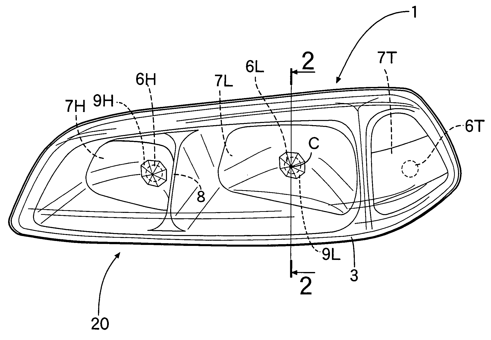
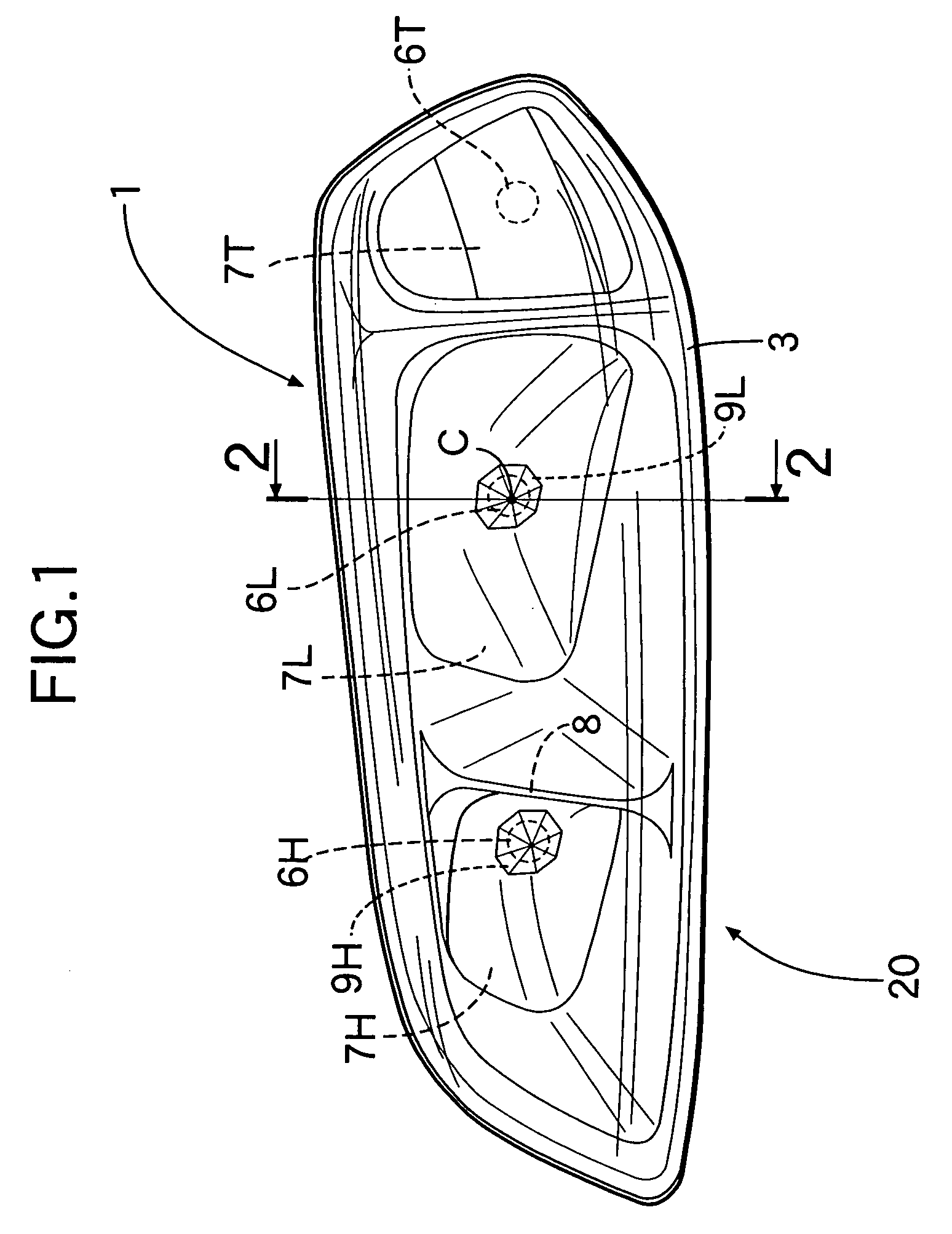
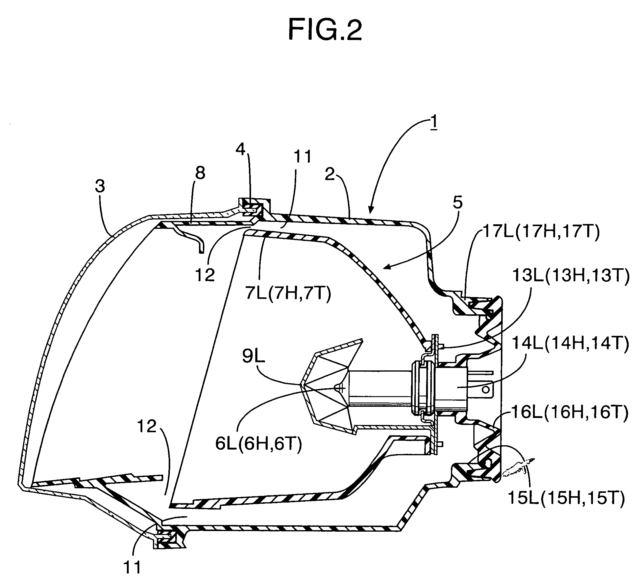
[0022]Referring firstly to FIG. 1 and FIG. 2, a housing 2 of a headlight 1 on the left side of an automobile is made in the form of a bowl that is open on a front face thereof, and a front face lens 3 is joined to an open end of the front face of the housing 2 via a seal 4. A laterally long housing chamber 5 is formed between the housing 2 and the front face lens 3, and a high beam bulb 6H, a low beam bulb 6L, and a turn signal bulb 6T are arranged in the housing chamber 5 in that order from the inside with respect to the lateral direction of the vehicle body.

[0023]Reflectors 7H, 7L, and 7T surrounding the corresponding bulbs 6H, 6L, and 6T and an integral partition hood 8 are contained within the housing chamber 5, the partition hood 8 separating front face openings of the reflectors 7H, 7L, and 7T from each other and being he...


PUM


Abstract

A headlight optical axis adjustment method where, on an imaged picture of a light distribution pattern of low beam illumination from a master headlight whose optical axis has been adjusted, a relative positional relationship between a horizontal and oblique line of a light / dark boundary line. A reference point is determined on the imaged picture to correspond to a bulb center. An acceptance frame is set based on an imaged position of an intersection of the horizontal and oblique line. On an imaged picture of a light distribution pattern of low beam illumination from a headlight to be adjusted, a horizontal and oblique line of a light / dark boundary line are detected based on a relative positional relationship with the reference point, and the optical axis of the headlight to be adjusted is adjusted so that an intersection of the detected horizontal and oblique lines is within the acceptance frame.

Description

FIELD OF INVENTIONCross-Reference to Related Application[0001]This application is a National Stage entry of International Application No. PCT / JP2004 / 002851, filed Mar. 5, 2004, the entire specification claims and drawings of which are incorporated herewith by reference.[0002]The present invention relates to a headlight optical axis adjustment method for adjusting a low beam optical axis of a headlight that has a vertically adjustable optical axis and, in particular, to a headlight optical axis adjustment method for adjusting a low beam optical axis of a headlight that has a vertically adjustable optical axis in a state in which the headlight is installed in an automobile, the method comprising carrying out in sequence a first step of, on an imaged picture of a light distribution pattern of low beam illumination from a master headlight whose optical axis has been adjusted, the picture being imaged at a predetermined distance in front of the master headlight, determining a relative po...

Claims


Application Information

Patent Timeline
Patent Type & Authority Patents(United States)
IPC IPC(8): F21V19/02G01M11/06
CPCG01M11/065G01M11/064
Inventor KIYOTA, HIROSHI
Owner HONDA MOTOR CO LTD
Why Eureka
Try Eureka