Angled tissue cutting instrument having variably positionable cutting window, indexing tool for use therewith and method of variably positioning a cutting window of an angled tissue cutting instrument

a tissue cutting and angled technology, applied in the field of angled tissue cutting instruments, can solve the problems of inability to rotate the distal end, the handpiece cannot be oriented for proper grasping and manipulation by the surgeon, and the directional positioning of the cutting window cannot be accomplished without, so as to achieve selective directional positioning of the cutting window during surgery, the effect of directional positioning of the cutting window and convenient us

Active Publication Date: 2007-10-02
MEDTRONIC XOMED INC
View PDF22 Cites 66 Cited by
  • Summary
  • Abstract
  • Description
  • Claims
  • Application Information

AI Technical Summary

Benefits of technology

[0014]The present invention also has as an object to prevent relative rotation between a distal end and elongate body of an outer member of an angled tissue cutting instrument when the outer member is in a longitudinally extended position and to permit relative rotation between the distal end and elongate body when the outer member is in a longitudinally retracted position to variably position a cutting window of the distal end.
[0027]The longitudinally extended and longitudinally retracted positions are obtained via relative longitudinal movement between the distal tip and the elongate body. In the longitudinally extended position, the distal tip is extended longitudinally distally from the forward end of the elongate body and, in the longitudinally retracted position, the distal tip is retracted longitudinally proximally relative to the elongate body. The outer member may be placed in the longitudinally extended position in response to distal advancement of the inner member within the outer member to a full insertion distance, causing distal extension of the distal tip from the elongate body. The outer member may be maintained or locked in the longitudinally extended position by the outer member and the inner member being releasably attached to a handpiece. The inner member may be withdrawn or moved proximally relative to the elongate body of the outer member a sufficient distance from its full insertion distance so that relative longitudinal movement is permitted between the distal tip and the elongate body by which the outer member may be placed in the longitudinally retracted position. The cutting window is maintained in a selected directional position by moving the outer member from the longitudinally retracted position to the longitudinally extended position. Movement of the outer member from the longitudinally retracted position to the longitudinally extended position may be accomplished in response to distal advancement of the inner member the full insertion distance within the outer member, thereby causing the body engagement structure to cooperatively interengage with the tip engagement structure with the cutting window in the selected directional position. Where the outer and inner members have been detached from the handpiece, reattachment of the outer and inner members to the handpiece secures the outer member in the longitudinally extended position in which the engagement structure prevents relative rotation between the distal tip and the elongate body about the central longitudinal axis.

Problems solved by technology

This situation presents disadvantages where access to an operative or cutting site is best established with the bend extending in a particular direction or orientation but the fixed position of the cutting window relative to the bend in the particular direction or orientation does not face the anatomical tissue intended to be cut with the instrument at the operative site.
Also, rotation of the entire instrument results in the handpiece being correspondingly rotated, such that the handpiece may no longer be oriented for proper grasping and manipulation by the surgeon.
Directional positioning of the cutting window cannot be accomplished without bending the bendable section and the distal end cannot be rotationally indexed about its central longitudinal axis.
The longitudinal profile of the outer member cannot be maintained and still allow variable directional positioning of the cutting window.
The bendable section and the intermediate member add undesired structural and functional complexity and cost to the instrument.

Method used


Image

  • Angled tissue cutting instrument having variably positionable cutting window, indexing tool for use therewith and method of variably positioning a cutting window of an angled tissue cutting instrument
  • Angled tissue cutting instrument having variably positionable cutting window, indexing tool for use therewith and method of variably positioning a cutting window of an angled tissue cutting instrument
  • Angled tissue cutting instrument having variably positionable cutting window, indexing tool for use therewith and method of variably positioning a cutting window of an angled tissue cutting instrument

Examples


Embodiment Construction

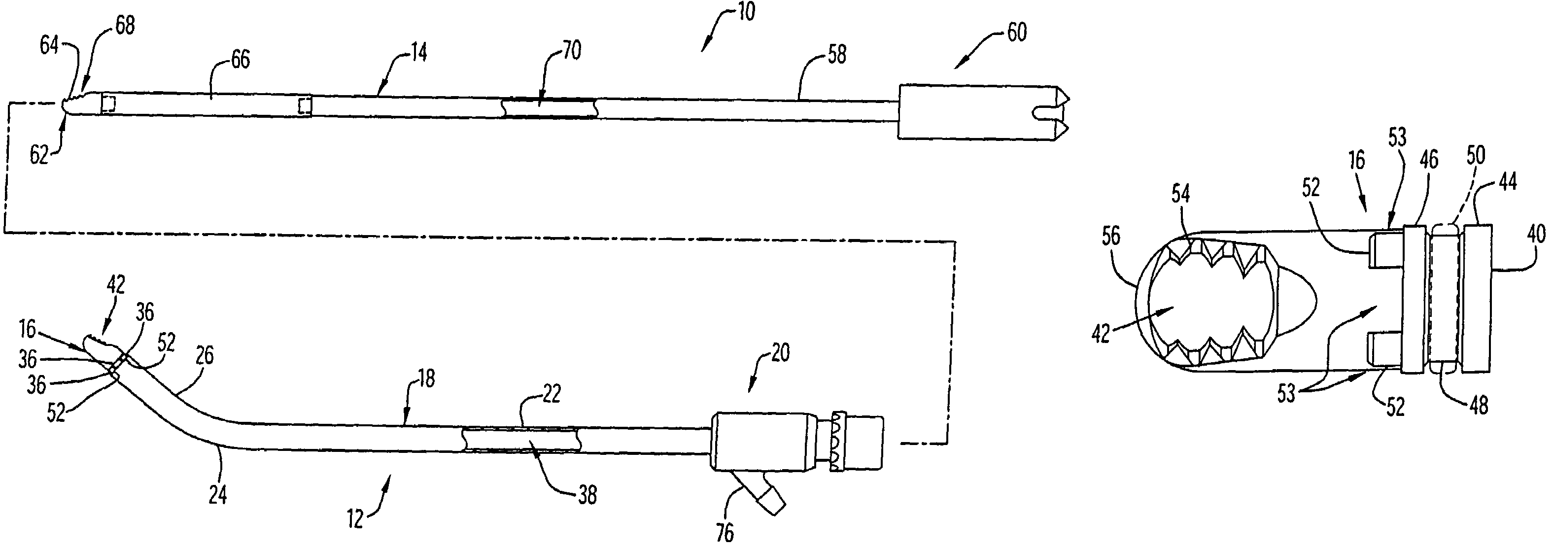
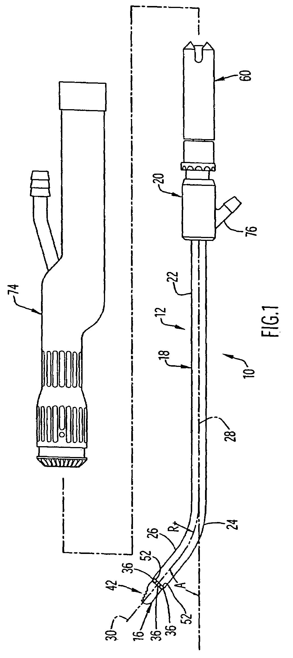
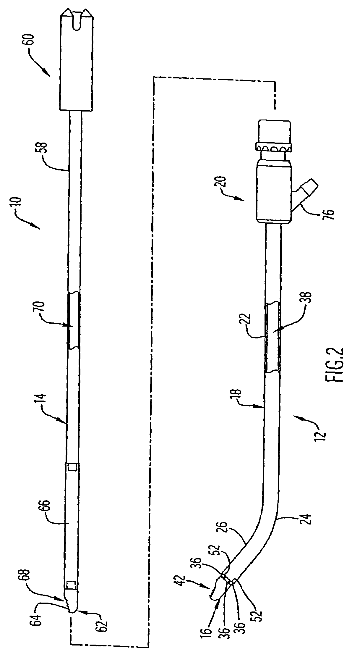
[0054]An angled tissue cutting instrument or blade 10 is illustrated in FIGS. 1 and 2 and includes an elongate outer tubular member 12 and an elongate inner member 14 rotatably or movably disposed within the outer member. Outer member 12, which may be considered an outer blade member, includes a distal end or tip 16 and an elongate body 18 having a forward end rotatably mounting distal tip 16. Body 18 has a rearward or proximal end coupled to an outer member hub 20, a proximal length portion 22 extending distally from outer member hub 20 to a bend, curve or angle 24, and a distal length portion 26 extending distally from bend 24 to the forward end at an angle A relative to a central longitudinal axis 28 of the proximal length portion. The proximal and distal length portions 22 and 26 are each shown as having a longitudinally or axially straight configuration with angle A defined between a central longitudinal axis 30 of the distal length portion and the central longitudinal axis 28 ...


PUM


Abstract

An angled tissue cutting instrument includes an outer member having an elongate body with a bend and a forward end, and a distal tip rotatably mounted on the forward end. The distal tip and body are rotatable relative to one another about a central longitudinal axis of the tip to variably position a cutting window of the tip in a selected directional position about the axis. Relative rotation between the distal tip and the body about the axis is prevented to lock the cutting window in a selected directional position when the outer member is maintained in a longitudinally extended position by an inner member of the instrument disposed within the outer member. An indexing tool for the angled tissue cutting instrument has a socket for receiving the distal tip to effect rotational indexing. A method of variably positioning a cutting window of an angled tissue cutting instrument involves rotationally indexing a distal tip of an outer member of the instrument and maintaining the distal tip in a selected rotationally indexed position.

Description

BACKGROUND OF THE INVENTION[0001]1. Field of the Invention[0002]The present invention relates generally to angled tissue cutting instruments including an elongate outer member having a bend and a distal end with a cutting window and, more particularly, to angled tissue cutting instruments in which the cutting window is variably positionable relative to the bend, to indexing tools for variably positioning the cutting windows of angled tissue cutting instruments, and to methods of variably positioning a cutting window of an angled tissue cutting instrument.[0003]2. Brief Discussion of the Related Art[0004]Tissue cutting instruments comprising an elongate outer tubular member and an elongate inner member rotatably disposed in the outer tubular member to cut anatomical tissue have become well-accepted for use in various surgical procedures. Typically, the inner member has a distal end with a cutting edge and the outer member has a distal end with a cutting window through which the cutti...

Claims


Application Information

Patent Timeline
Patent Type & Authority Patents(United States)
IPC IPC(8): A61B17/32A61B17/00A61B17/28
CPCA61B17/32002A61B2017/00296A61B2017/2929A61B2017/2904A61B2017/00455
Inventor ADAMS, KENNETH M.MITUSINA, MIRO
Owner MEDTRONIC XOMED INC
Why Eureka
Try Eureka