Dispenser for pressurized beverage bottle

a technology for beverage bottles and dispensers, applied in the field of sealing pressurized bottles, can solve problems such as limited effervescen

Active Publication Date: 2010-01-07
PUMA SAMUEL C
View PDF4 Cites 28 Cited by
  • Summary
  • Abstract
  • Description
  • Claims
  • Application Information

AI Technical Summary

Benefits of technology

[0006]The present invention addresses the above and other needs by providing a beverage release cap residing over a bottle cap of a plastic carbonated beverage bottle for selectively dispensing a beverage, without losing gases inside the bottle. The beverage release cap allows the carbonated beverage to be dispensed without the release of evolved gas within the bottle when the bottle is inverted or partially inverted for pouring. The beverage release cap has three distinct functional and physical sections. A lower section engaging a bottle rim below the bottle cap and snapping over the bottle rim, thereby retaining the beverage release cap to the bottle while providing a seal and permitting a twisting rotation of the beverage release cap. A middle section gripping the bottle cap with vertical, equally spaced ribs, a space between the ribs allowing beverage to flow between the bottle cap and the beverage release cap. An upper section providing a pouring spout and a path for the beverage to flow from the middle section to the spout. Functionally, the beverage release cap is secured over the bottle cap of the beverage bottle containing a gas charged liquid. The bottle is then inverted sufficiently to keep the neck of the bottle filled with the beverage. The beverage release cap is twisted while engaging the bottle cap, which loosens the bottle cap. The loosening breaks a pressure seal and allows dispensing of the beverage into a suitable container without releasing the gases in the bottle. The beverage release cap is then twisted to close the bottle cap before returning the bottle to an upright position. The beverage release cap may alternatively be a replacement to the standard bottle cap.

Problems solved by technology

Carbon dioxide gas will effervesce out of the remaining beverage to fill the void created as the beverage is dispensed, but such effervesce is limited because the void is quickly filled and gas pressure equilibrium is reached without the beverage losing a noticeable amount of carbonation.

Method used


Image

  • Dispenser for pressurized beverage bottle
  • Dispenser for pressurized beverage bottle
  • Dispenser for pressurized beverage bottle

Examples


Embodiment Construction

[0026]The following description is of the best mode presently contemplated for carrying out the invention. This description is not to be taken in a limiting sense, but is made merely for the purpose of describing one or more preferred embodiments of the invention. The scope of the invention should be determined with reference to the claims.

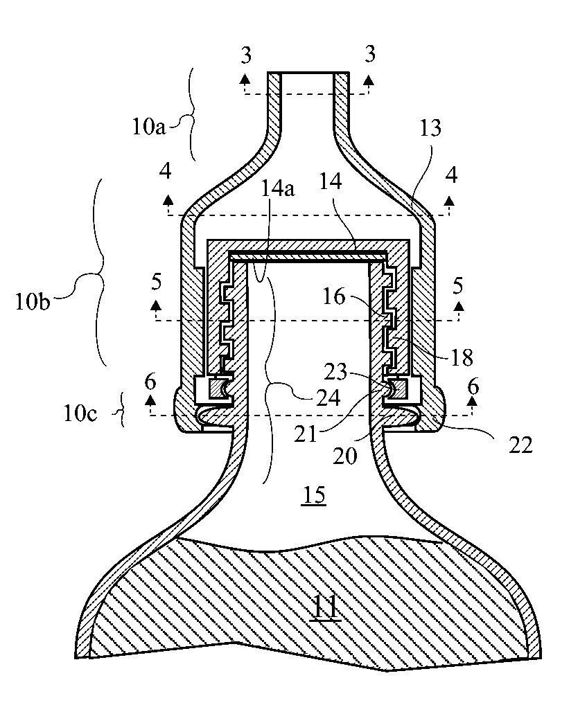
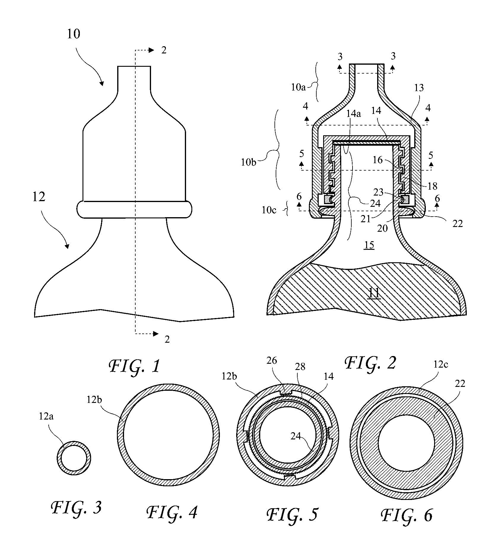
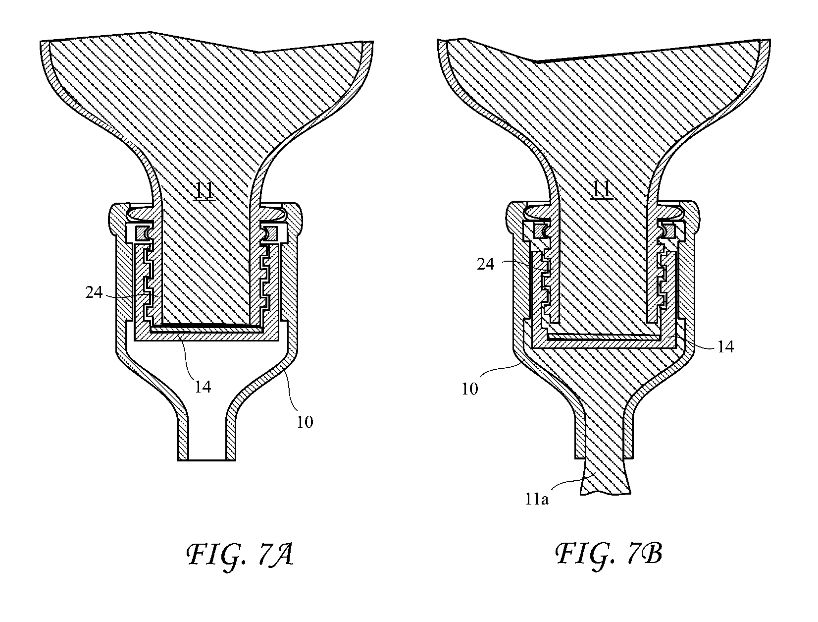
[0027]A side view of a beverage release cap 10 according to the present invention on a carbonated beverage bottle 12 is shown in FIG. 1 and a vertical cross-sectional view of the beverage release cap 10 on the carbonated beverage bottle 12 taken along line 2-2 of FIG. 1 is shown in FIG. 2. Additionally, a horizontal cross-sectional view of the beverage release cap 10 taken along line 3-3 of FIG. 2 is shown in FIG. 3, a horizontal cross-sectional view of the beverage release cap 10 taken along line 4-4 of FIG. 2 is shown in FIG. 4, a horizontal cross-sectional view of the beverage release cap 10, a bottle cap 14, and a bottle neck 24 taken along li...


PUM


Abstract

A beverage release cap over a bottle cap of a plastic carbonated beverage bottle for dispensing a beverage, without losing gasses inside the bottle, when the bottle is inverted or partially inverted for pouring. The beverage release cap has three distinct functional and physical sections. A lower section engaging a bottle rim below the bottle cap and snapping over the bottle rim, thereby retaining the beverage release cap to the bottle while providing a seal and permitting a twisting rotation of the beverage release cap. A middle section gripping the bottle cap with vertical, equally spaced ribs, a space between the ribs allowing beverage to flow between the bottle cap and the beverage release cap. An upper section providing a path for the beverage to flow from the middle section. The beverage release cap may alternatively be a replacement to the standard bottle cap.

Description

[0001]The present application claims the priority of U.S. Provisional Patent Application Ser. No. 61 / 078,366 filed Jul. 4, 2008, which application is incorporated in its entirety herein by reference.BACKGROUND OF THE INVENTION[0002]The present invention relates to sealing pressurized bottles and in particular to retaining carbonation in carbonated beverage bottles after opening.[0003]Carbonated beverages are enjoyed with meals, as a refreshment between meals, at sporting events, and at parties. Carbonated beverages are available in single small cans, for example, 12 ounce cans, 16 and 20 ounce bottles, and larger economy sized bottles. The large economy sized bottles are generally sold for a lower per ounce price than small container sizes.[0004]The large economy sized bottles have a plastic rigid screw cap which seals to a screw-threaded neck. When the cap is unscrewed to pour the beverage, the pressurized carbon dioxide gas on top of the liquid is released into the atmosphere. The...

Claims


Application Information

Patent Timeline
Patent Type & Authority Applications(United States)
IPC IPC(8): B67D5/00B65B7/28B65D53/00
CPCB65D47/06B65D47/263B65D47/242
Inventor PUMA, SAMUEL C.
Owner PUMA SAMUEL C
Why Eureka
Try Eureka