Modular apparatus for assembling tubular goods

a module apparatus and tubular goods technology, applied in the direction of drilling pipes, drilling rods, borehole/well accessories, etc., can solve the problems of inability to convert from one method to the other, high cost, and long work time, and achieve the effect of quick, efficient and safe assembling and installation, quick modification, and convenient actuation of the r

Inactive Publication Date: 2014-11-25
HENDERSON KRIS +2
View PDF9 Cites 29 Cited by
  • Summary
  • Abstract
  • Description
  • Claims
  • Application Information

AI Technical Summary

Benefits of technology

[0014]In the preferred embodiment, the present invention comprises a modular RT that can be used in connection with top drive systems to quickly, efficiently and safely assemble and install tubular goods (including, without limitation, large diameter or heavy weight casing) into a well. The modular RT of the present invention can permit gripping of pipe either internally (i.e., within the internal bore of such pipe) or externally (i.e., on the outer surface of such pipe). By simply changing out certain modular components, the tool can be quickly modified between an internal and an external gripping tool that allows gripping of larger diameter pipe.
[0015]The RT of the present invention further comprises a dynamic fluid swivel that conveys control fluid (typically hydraulic oil) to different parts of the RT in order to facilitate actuation of said RT, while permitting rotation of said RT and the application of torque to pipe gripped by said RT. However, the RT of the present invention isolates elevated control fluid pressures from such swivel during rotation of the RT. As a result, the fluid seals of said fluid swivel last much longer than conventional swivel seal assemblies, while permitting rotation at much higher rates than conventional RT's.

Problems solved by technology

However, drilling rate is not the only variable affecting operational costs; pipe string assembly and installation rate typically has about the same cost-effect as drilling rate.
The rate of assembly and installation of the casing can amount to many hours of total work time which, in turn, equates to higher costs.
However, because such functions generally require very different RT equipment configurations, most RT systems are designed for either internal gripping of pipe or external gripping of pipe, but cannot be converted from one method to the other.
Further, existing RT systems generally provide for relatively low rotational rate (rpm), primarily due to limitations associated with hydraulic swivel seals.

Method used


Image

  • Modular apparatus for assembling tubular goods
  • Modular apparatus for assembling tubular goods
  • Modular apparatus for assembling tubular goods

Examples


Embodiment Construction

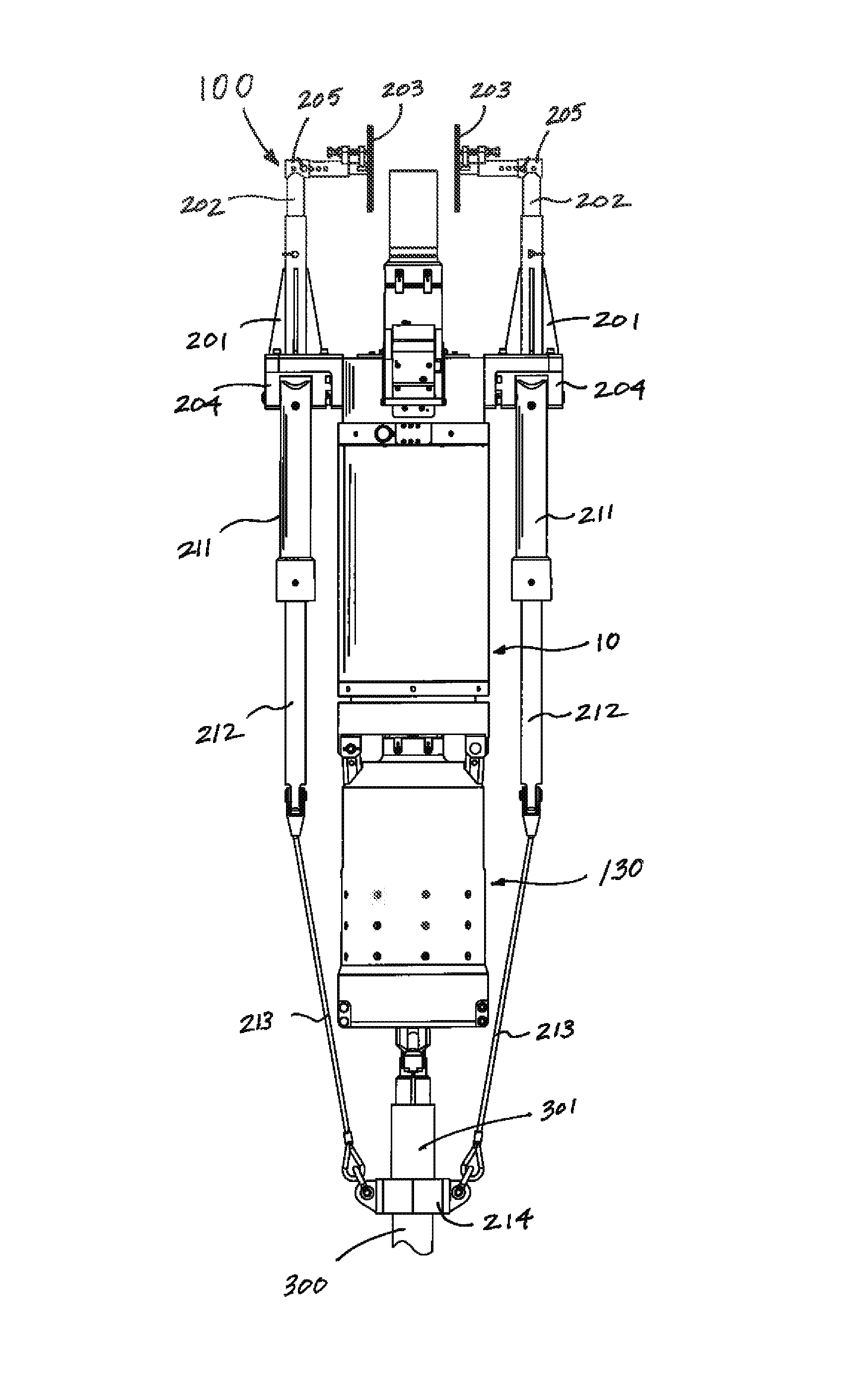
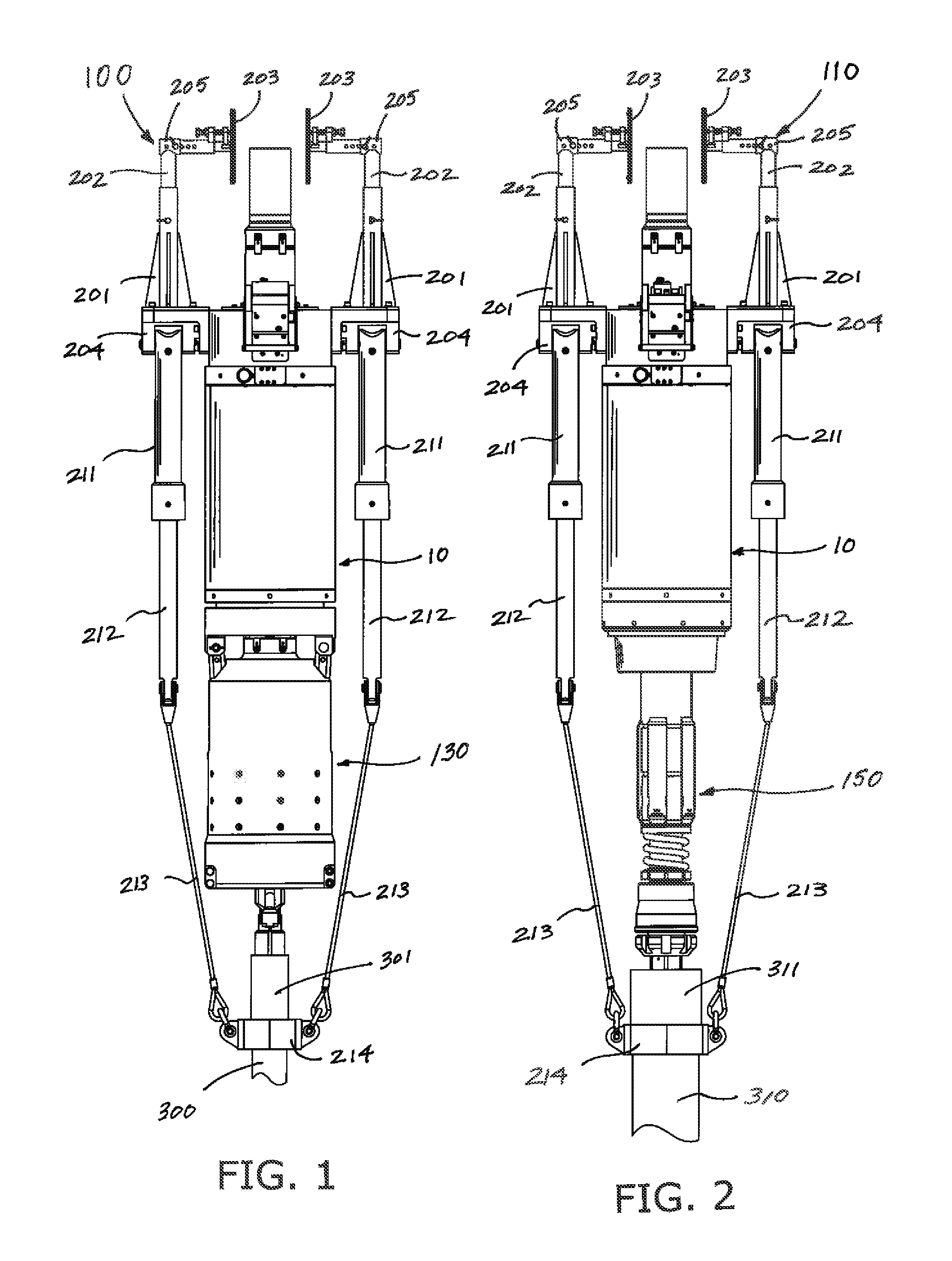
[0041]Referring to the drawings, FIG. 1 depicts modular pipe running assembly 100 of the present invention configured for gripping against the external surface of a length of pipe. FIG. 2 depicts alternative embodiment modular pipe running assembly 110 of the present invention configured for gripping against the internal surface of a length of pipe.

[0042]As depicted in FIG. 1, modular pipe running assembly 100 can be connected beneath a rig's existing top drive assembly, and generally comprises axially aligned modular actuator assembly 10 and external pipe gripping assembly 130. In the embodiment depicted in FIG. 2, modular pipe running assembly 110 comprises many of the same components as modular pipe running assembly 100 depicted in FIG. 1, except that internal pipe gripping assembly 150 is connected to actuator assembly 1, rather than external pipe gripping assembly 130.

[0043]Referring to FIG. 1, in the preferred embodiment modular pipe gripping assembly 100 has an adjustable mou...


PUM


Abstract

A modular pipe gripping assembly has a universal actuator assembly having a control fluid swivel. An external pipe gripping assembly can be attached to the actuator assembly for gripping the external surface of a section of pipe. Alternatively, the external pipe gripping assembly can be quickly and easily removed and replaced with an internal pipe gripping assembly for gripping the internal surface of a section of pipe. Control fluid pressure is trapped within the actuator assembly, but relieved from a fluid swivel, permitting high speed rotation of the modular pipe gripping assembly and preserving swivel seal life.

Description

CROSS REFERENCES TO RELATED APPLICATION[0001]Priority of U.S. Provisional Patent Application Ser. No. 61 / 528,350, filed Aug. 29, 2011, incorporated herein by reference, is hereby claimed.STATEMENTS AS TO THE RIGHTS TO THE INVENTION MADE UNDER FEDERALLY SPONSORED RESEARCH AND DEVELOPMENT[0002]NONEBACKGROUND OF THE INVENTION[0003]1. Field of the Invention[0004]The present invention pertains to an apparatus for assembling and installing pipe in a well. More particularly, the present invention pertains to a pipe running tool that can rotate at high speed, and selectively grip pipe either internally or externally. More particularly still, the present invention pertains to a pipe running tool that can be quickly and easily converted between internal and external pipe gripping simply by changing out modular components.[0005]2. Brief Description of the Prior Art[0006]Efficiency in connection with oil and gas operations, especially in terms of drilling rate, has been addressed with great ear...

Claims


Application Information

Patent Timeline
Patent Type & Authority Patents(United States)
IPC IPC(8): E21B19/02E21B19/24E21B19/08E21B19/00E21B19/16
CPCE21B19/08E21B19/16E21B19/00E21B19/02E21B19/06
Inventor HENDERSON, KRISMATHERNE, JR., LEE J.ROBICHAUX, LEE M.
Owner HENDERSON KRIS
Why Eureka
Try Eureka