Wind turbine - floating platform assembly and method for orienting said assembly description

a technology of floating platforms and wind turbines, which is applied in the direction of engine control parameters, self-bailing equipment/scuppers, buoyancy control, etc., can solve the problems of increasing the weight of the blades and the tower, and increasing the weight of the rotor

Active Publication Date: 2012-07-05
NORDEX ENERGY SPAIN SA
View PDF3 Cites 28 Cited by
  • Summary
  • Abstract
  • Description
  • Claims
  • Application Information

AI Technical Summary

Benefits of technology

[0002]The present invention can be included within the technical field of wind

Problems solved by technology

This last design trend has the drawback that, in upwind-type horizontal-axis wind turbines, deflection of the blades produced by strong winds tends to push the tip of the blades towards the tower, which would cause irreparable damage to the blades and to the tower in case of contact therewith.
However, providing the blades with a high degree of rigidity implies increasing their weight and therefore price.
Additionally, the greater weight of the rotor implies an increase in the cost of other structural parts of the wind turbine and platform.
A double drawback of using rotors mounted with a tilt angle greater than zero is that the performance of the machine is modified proportionally to the cube of the cosin

Method used


Image

  • Wind turbine - floating platform assembly and method for orienting said assembly description
  • Wind turbine - floating platform assembly and method for orienting said assembly description
  • Wind turbine - floating platform assembly and method for orienting said assembly description

Examples


first embodiment

[0046]FIG. 5.—Shows a view of the orientation means according to the

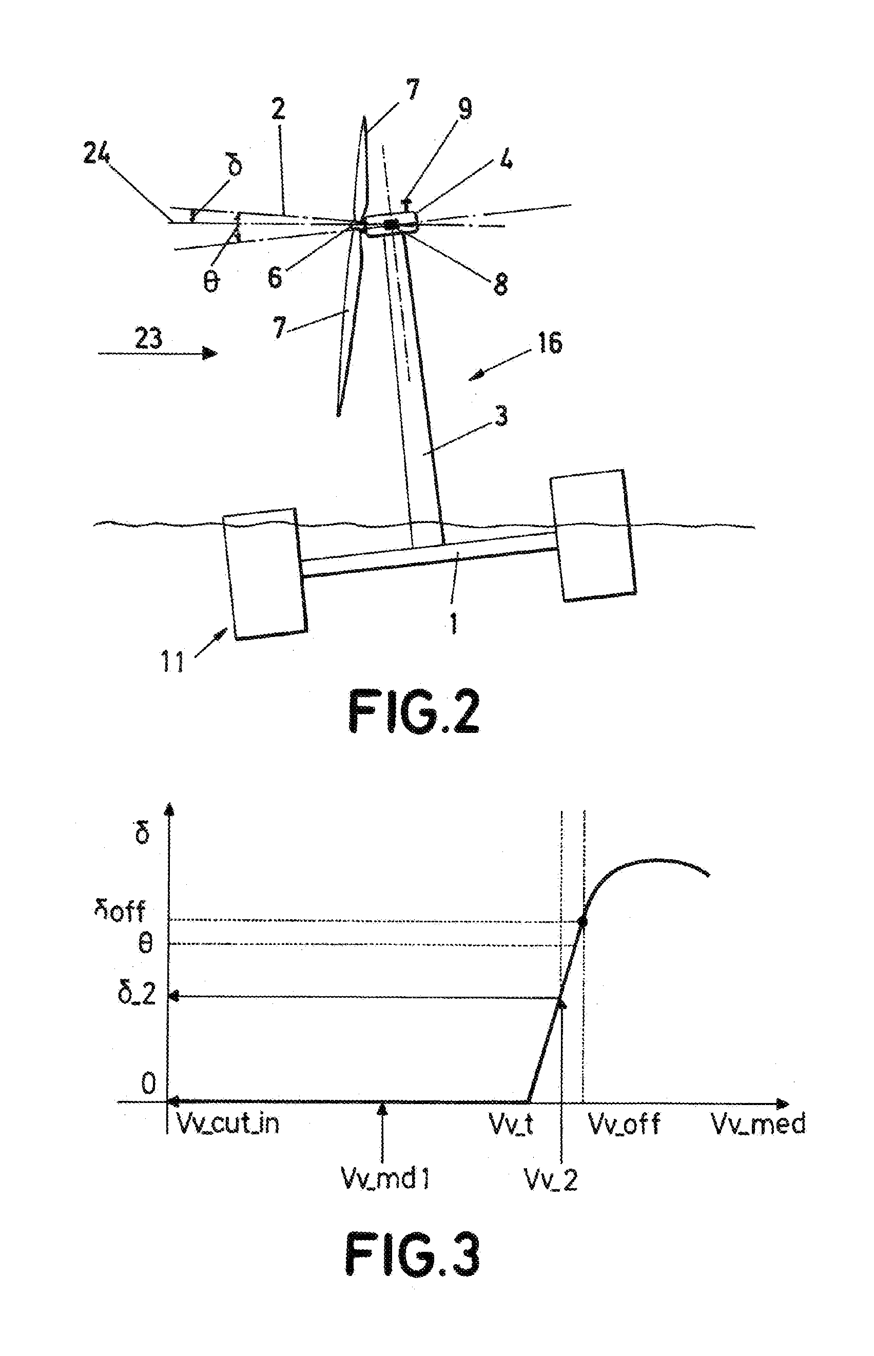
[0047]FIG. 6.—Shows a schematic view of the operation of the method according to a preferred embodiment.

PREFERRED EMBODIMENTS OF THE INVENTION

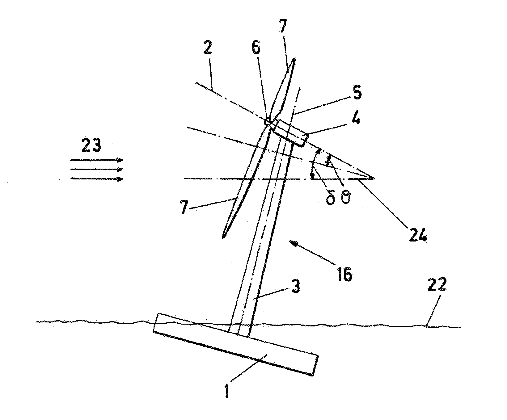
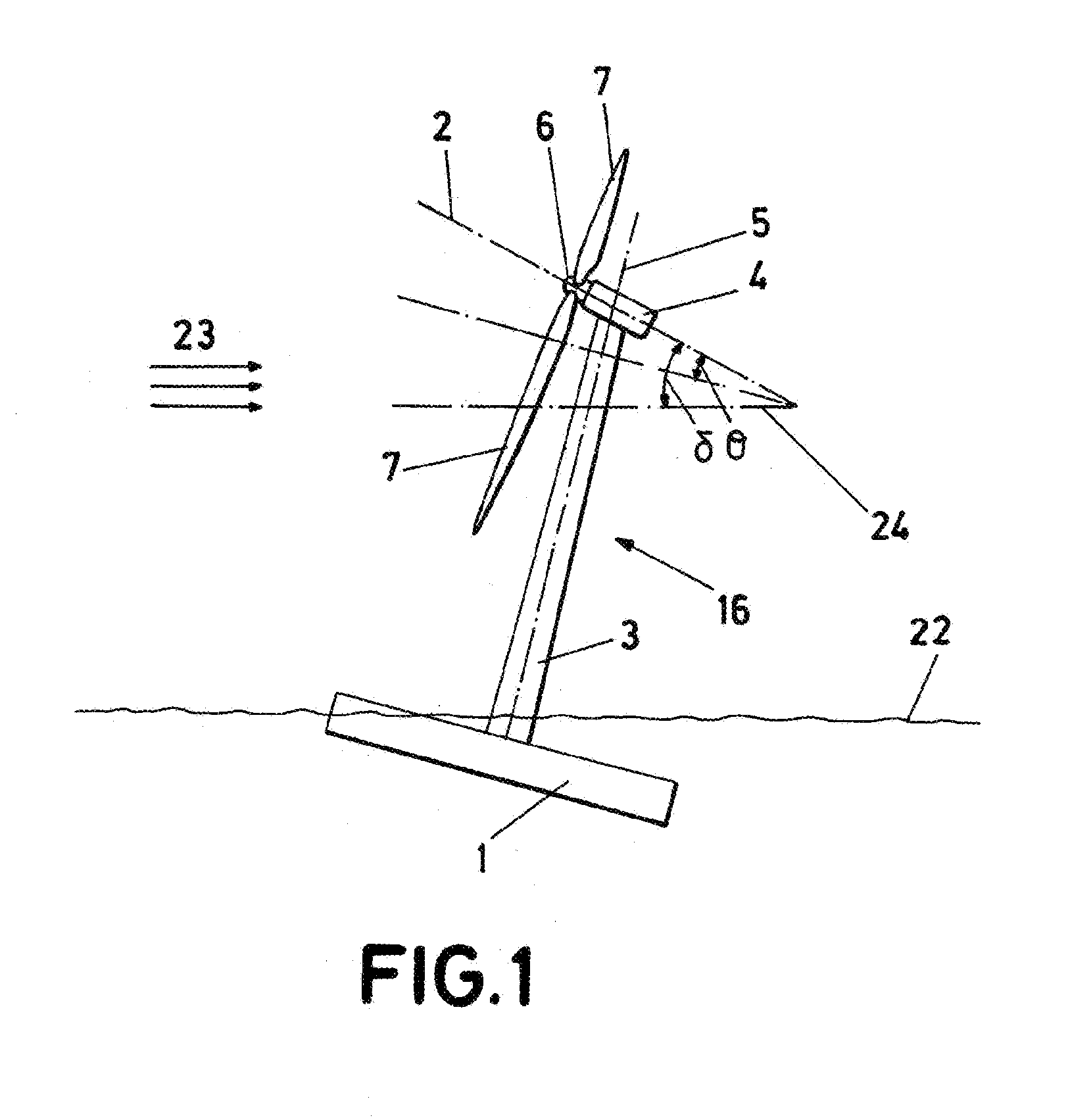
[0048]The wind turbine (16)—floating platform (1) assembly in accordance with the invention shown in FIG. 2 comprises an upwind-type wind turbine (16) disposed on a floating platform (1), where the wind turbine comprises:[0049]a tower (3) fixed to the platform (1);[0050]a nacelle (4) disposed on the tower (3) for supporting a rotor (6), and having a yaw mechanism (not shown) to orient the rotor (6) windward, said yaw mechanism enabling the nacelle (4) to rotate with respect to the tower (3) around the longitudinal axis of said tower (3); the rotor (6) comprising at least two blades (7) capable of making the rotor (6) rotate around a rotation axis (2) due to the action of the wind incident upon said blades (7), the rotation axis (2) having a tilt angle (θ), formed between the r...

second embodiment

[0066]In accordance with a second embodiment, the method of the invention comprises the additional steps of:[0067]capturing a third input (15) by means of the third sensors (10);[0068]communicating said third input (15) to the control unit (12); and[0069]comparing the value of the third input (15) to the previously defined threshold value and, when the condition that the value of the third input (15) does not exceed the threshold value is fulfilled, ordering the orientation means to orient the platform in accordance with the first input (13), the second input (14) and the third input (15).

[0070]In a third preferred embodiment of the invention, a third input signal is used for controlling leaning, said signal being selected from among the following: wind speed, rotor rotation speed, electricity generated or blade pitch angle.

[0071]Control of the angle of blade pitch towards feathered position to control rotor rotation speed within the rated wind range is typical in wind turbines. The...


PUM


Abstract

The invention allows orientation of the platform (1) in order to obtain conditions of maximum efficiency in the wind turbine (16). It comprises first sensors (8) for detecting an effective rotation axis angle (δ) formed between the rotation axis (2) and a horizontal plane (24); second sensors (9) for detecting wind direction (23); platform orientation means (11) for modifying the effective rotation axis angle (δ); and at least one control unit (12) adapted for receiving a first input (13) from the first sensors (8) and a second input (14) from the second sensors (9) and, based on said inputs (13, 14), transmitting orders to the platform orientation means (11) and yaw mechanism.

Description

[0001]This application claims benefit of Serial No. P201031996, filed 29 Dec. 2010 in Spain and which application is incorporated herein by reference in its entirety.OBJECT OF THE INVENTION[0002]The present invention can be included within the technical field of wind energy, more specifically, using wind turbines disposed on floating platforms.[0003]The object of the present invention relates to an assembly formed by a wind turbine and a floating platform whereupon said wind turbine is disposed, as well as a process for orienting said assembly.BACKGROUND OF THE INVENTION[0004]The so-called horizontal axis wind turbines, used for transforming wind energy into electricity, comprise, as is already known, a tower, a nacelle and a wind rotor having at least two blades. Due to the action of the wind incident upon the blades, the rotor rotates around an axis which orientation is substantially horizontal with respect to the ground. In turn, the nacelle can rotate around the longitudinal axi...

Claims


Application Information

Patent Timeline
IPC IPC(8): F03D7/02
CPCF03D7/0204F03D11/04F05B2240/93F05B2270/18B63B39/02F05B2270/326F05B2270/33Y02E10/723Y02E10/727F05B2270/321B63B13/00B63B43/06F03D13/25Y02E10/72
Inventor GABEIRAS, TERESA ARLABANSAYES, JOSE MIGUEL GARCIAPOLO, MIGUEL N NEZ
Owner NORDEX ENERGY SPAIN SA
Why Eureka
Try Eureka