Method of inserting surgical implant with guiding rail

a technology of surgical implants and guiding rails, which is applied in the field of spinal implants, can solve the problems of thinning of discs, abnormal movement, and affecting the visibility of surgical sites, and achieve the effect of preventing relative rotation

Active Publication Date: 2013-12-10
SPINE STRYKER
View PDF122 Cites 29 Cited by
  • Summary
  • Abstract
  • Description
  • Claims
  • Application Information

AI Technical Summary

Benefits of technology

[0017]In accordance with other embodiments of the fifth aspect, the method may further include the steps of inserting the spacer into the intervertebral disc space, disengaging the first end of the rod from the notch, and / or further inserting the spacer into the intervertebral space when the rod is disengaged from the notch. The tool may be configured to slide along the interface of the spacer when engaged with the spacer, where the step of further inserting the spacer includes sliding the tool along the interface of the spacer while the spacer rotates in the intervertebral disc space. Relative rotation of the spacer may be prevented when the rod is engaged to the notch and permitted when the rod is disengaged from the notch. The step of disengaging may be conducted when the spacer contacts a portion of an annulus fibrosis in the anterior portion of the intervertebral disc space.
[0020]In accordance with embodiments of the sixth aspect, the method may further include the steps of inserting the spacer into the intervertebral space, disengaging the rod from the notch, and / or further inserting the spacer into the intervertebral space when the rod is disengaged from the notch. In further embodiments, the tool may be configured to slide along the interface of the spacer when engaged with the spacer, with the step of further inserting the spacer includes sliding the tool along the interface of the spacer while the spacer rotates in the intervertebral disc space. Relative rotation between the spacer and the tool may be prevented when the rod is engaged to the notch and permitted when the rod is disengaged from the notch. The step of disengaging may be conducted when the spacer contacts the annulus fibrosis in the anterior portion of the intervertebral disc space.
[0024]An eighth aspect of the present invention is another method of inserting and positioning a prosthetic intervertebral spacer in an intervertebral disc space between two adjacent vertebrae. In accordance with one embodiment of the eighth aspect, the method may include the steps of providing a spacer including a body having a front end, a rear end, a longitudinal axis, and an interface extending away from the body and being connected to the rear end of the body, the interface including a notch; engaging a tool to be interface, the tool including a rod; engaging the rod to the notch to prevent relative rotation between the spacer and the tool; inserting the spacer at least partially into the intervertebral disc space by moving the tool along an insertion direction; disengaging the rod from the notch; inserting the spacer further into the intervertebral disc space after the disengaging step by moving the tool substantially along the insertion direction; and allowing the spacer to rotate with respect to the insertion direction within the intervertebral disc space when the rod is disengaged from the notch while continuing to move the tool along the insertion direction.

Problems solved by technology

These disc problems include, for instance, degeneration, bulging, herniation, thinning of a disc, and abnormal movement, and the pain that is experienced is generally attributable to friction or pressure that inevitably occurs when one adjacent vertebra exerts uneven pressure or when both adjacent vertebrae exert such pressure on the disc.
Oftentimes, disc problems lead to the vertebrae impinging on one of the very many nerves located in the spinal column.
One major issue that has existed and will continue to exist is the fact that visibility to the surgical site is often hindered by the patient anatomy.
For instance, in the cervical section of the spine, the vertebral bodies are rather small and surrounding patient anatomy, such as the esophagus and other body parts, makes access to and visibility of the surgical site rather difficult.
This often hinders the surgeon in properly positioning an implant with respect to the vertebrae.
Furthermore, in many IF procedures, the required manipulation of the patient anatomy, distraction of the vertebral bodies, and preparation of the vertebral bodies often results in significant scar tissue being formed in the patient.
This can be detrimental when performing any subsequently required spinal procedures.

Method used


Image

  • Method of inserting surgical implant with guiding rail
  • Method of inserting surgical implant with guiding rail
  • Method of inserting surgical implant with guiding rail

Examples


Embodiment Construction

[0047]In describing the preferred embodiments of the subject illustrated and to be described with respect to the drawings, specific terminology will be used for the sake of clarity. However, the invention is not intended to be limited to any specific terms used herein, and it is to be understood that each specific term includes all technical equivalents that operate in a similar manner to accomplish similar purpose.

[0048]As used herein, when referring to bones or other parts of the body, the term “proximal” means closer to the heart and the term “distal” means more distant from the heart. The term “inferior” means toward the feet and the term “superior” means towards the head. The term “anterior” means towards the front part of the body or the face and the term “posterior” means towards the back of the body. The term “medial” means toward the midline of the body and the term “lateral” means away from the midline of the body.

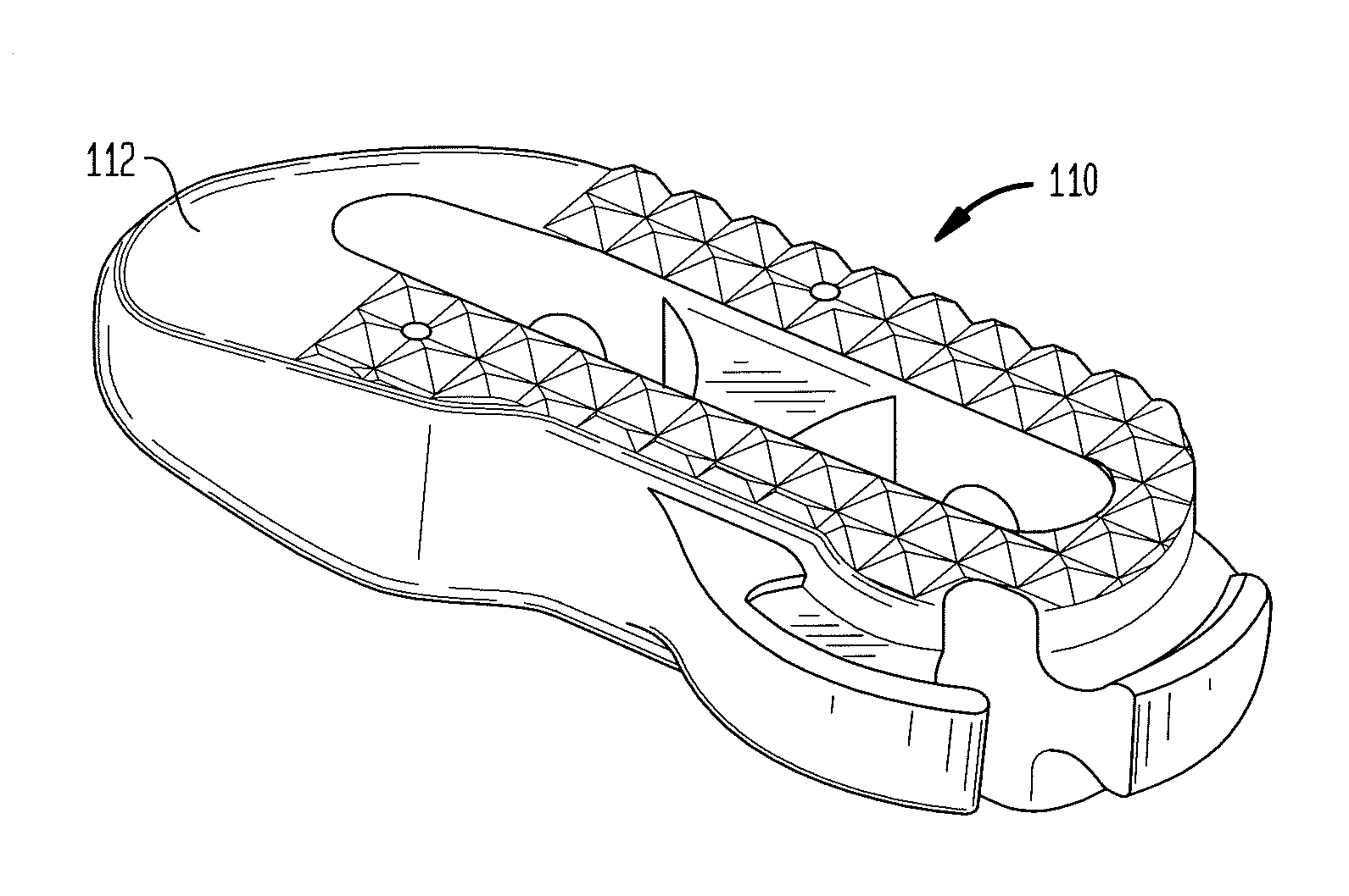
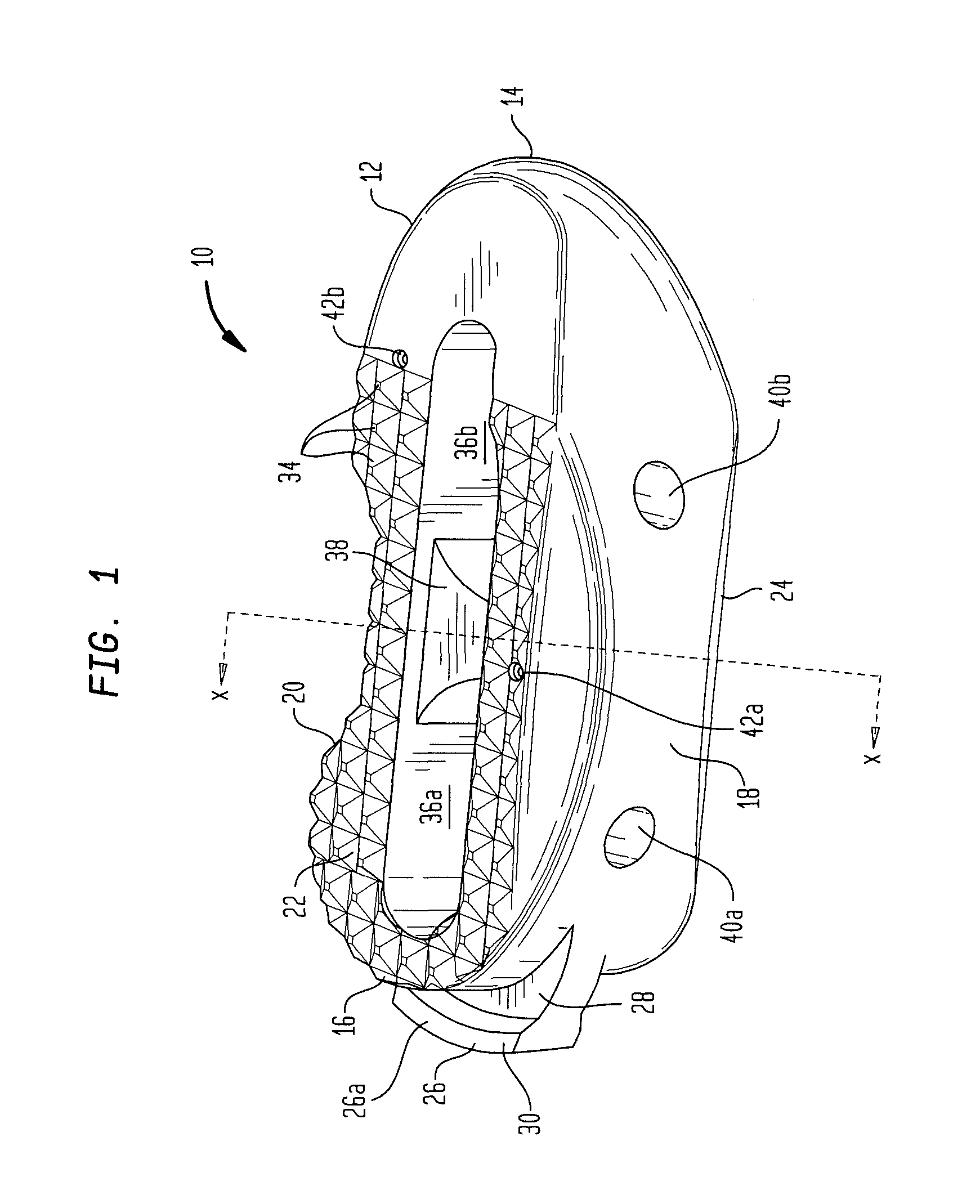
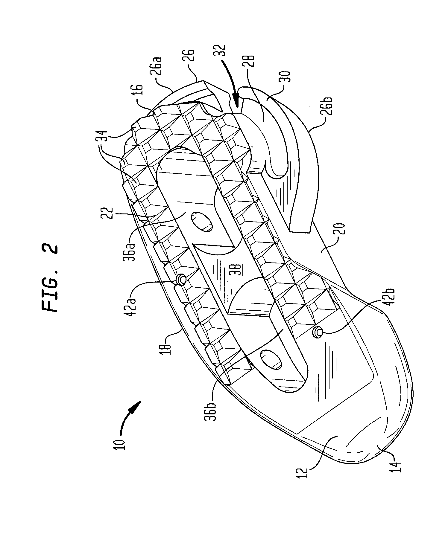
[0049]Referring to FIGS. 1-4, there is shown a prosthetic i...


PUM


Abstract

A prosthetic intervertebral spacer includes a body and an interface extending away from the body for use during implantation of the spacer. The interface can be a rail including a neck portion connected to the body and a lip portion connected to the neck portion. The lip portion can be wider than the neck portion in a direction extending between the top and bottom surfaces of the implant. Methods of implanting the spacer and tools used during such procedure are also provided.

Description

BACKGROUND OF THE INVENTION[0001]The present invention relates to spinal implants and methods of implanting such implants. More particularly, the present invention relates to a spinal implant having a guiding rail for cooperating with an insertion instrument, as well as the methods associated with implanting that implant.[0002]Back pain can be caused by many different things, including any one of several problems that affect the intervertebral discs of the spine. These disc problems include, for instance, degeneration, bulging, herniation, thinning of a disc, and abnormal movement, and the pain that is experienced is generally attributable to friction or pressure that inevitably occurs when one adjacent vertebra exerts uneven pressure or when both adjacent vertebrae exert such pressure on the disc. Oftentimes, disc problems lead to the vertebrae impinging on one of the very many nerves located in the spinal column.[0003]One surgical method commonly utilized to correct such disc prob...

Claims


Application Information

Patent Timeline
Patent Type & Authority Patents(United States)
IPC IPC(8): A61F2/44
CPCA61F2/4465A61F2/4611A61F2002/3008A61F2002/30538A61F2002/30843A61F2002/30878A61F2002/4622A61F2002/4627A61F2002/2817A61F2002/2835A61F2002/30266A61F2002/30304A61F2002/30777A61F2002/30779A61F2002/30785A61F2002/3082A61F2002/30879A61F2002/30883A61F2002/30593
Inventor THIBODEAU, LEE L.
Owner SPINE STRYKER
Why Eureka
Try Eureka