Rotatable coupler for endoscopic camera

a technology of endoscopic camera and rotatable coupler, which is applied in the field of endoscope couplers, can solve the problems of affecting the performance of all known rotatable endoscopic couplers, and not being able to withstand the steam autoclave process

Active Publication Date: 2006-10-12
LINVATEC
View PDF13 Cites 28 Cited by
  • Summary
  • Abstract
  • Description
  • Claims
  • Application Information

AI Technical Summary

Benefits of technology

[0019] These and other objects are accomplished by the preferred embodiment disclosed herein which is a rotatable coupler for coupling a camera to an optical assembly, preferably an endoscopic optical assembly. The coupler comprises a proximal camera attachment means for fixedly securing the coupler to a camera, a distal optical assembly attachment means for fixedly securing the coupler to an optical assembly and a selectively rotatable coupling means interposed between the camera attachment means and the optical assembly attachment means. In one embodiment, the rotatable coupling means comprises a first annular member which is fixedly connected to the optical assembly attachment means and a second annular member is fixedly secured to the camera attachment means. An annular ball bearing means is interposed between the first and second annular members to permit relative rotation therebetween. The first annular member has a plurality of radially inwardly directed slots and a locking means attached to the second annular member annular member is adapted to selectively engage the slots to lock the first annular member to the second annular member.

Problems solved by technology

Instruments that will not survive the steam autoclave process, such as video cameras and prior art endoscopic couplers are treated by less effective or less efficient means such as immersion in sterilization liquid or gas sterilization.
However, there is no known conventional rotatable endoscopic coupler which can withstand repeated steam or other sterilization and all known rotatable endoscopic couplers are adversely affected by such.
Over time, these known rotatable coupler designs become more and more difficult to operate because of the build up of residue caused by improper cleaning as well as the deterioration of the cooperating parts caused by their exposure to the harsh environments of autoclaves.
This deterioration eventually leads to the inability to easily operate the rotatable coupler with one hand and eventually leads to the inability to rotate the coupler at all.

Method used


Image

  • Rotatable coupler for endoscopic camera
  • Rotatable coupler for endoscopic camera
  • Rotatable coupler for endoscopic camera

Examples


Embodiment Construction

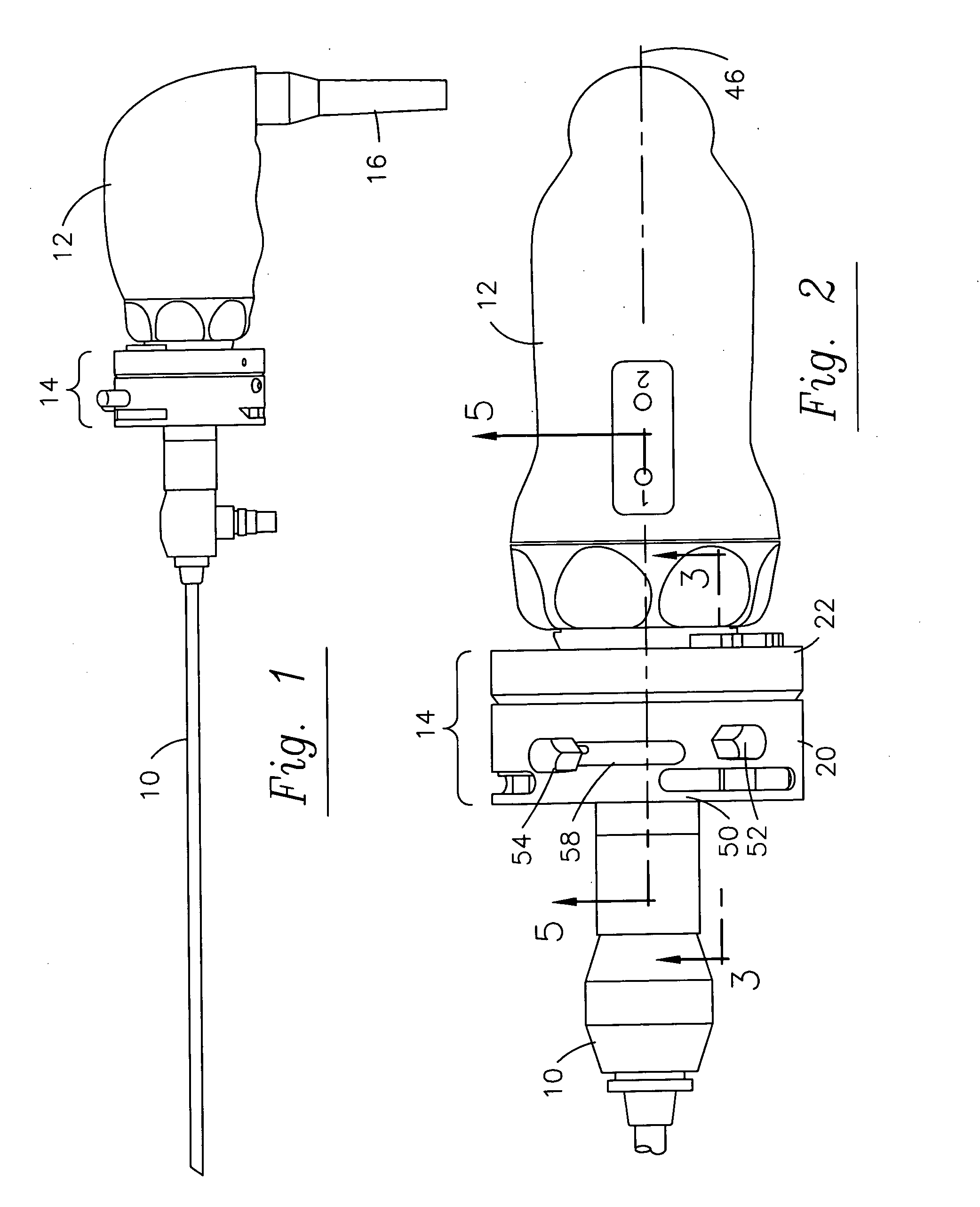
[0034]FIGS. 1 and 2 show an endoscope 10 releasably connected to a camera head 12 via an intermediate rotatable coupler assembly 14 constructed in accordance with the principles of this invention.

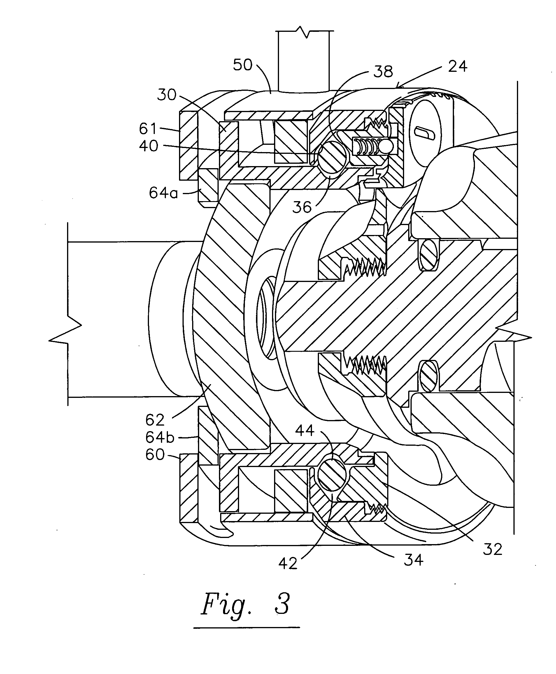
[0035] Coupler assembly 14 comprises a distal cylindrical “grabber” means 20, which is releasably attachable to the eyepiece of scope 10, and a proximal camera mount means 22 which, in the preferred embodiment is fixedly attached to camera 12. Grabber means 20 is selectively rotatable relative to camera mount means 22 by virtue of interface or bearing means 24 interposed therebetween, as best seen in FIG. 3. The freely rotatable grabber means enables a user to permit the camera head 12 (and, therefore, the monitor view) to remain fixed in selected orientation (e.g. upright), while rotating the scope about axis 46. Either the scope or the camera may be rotated about the axis with the fingers of the hand holding the camera head. For applications such as urology, for example, the surgeon need...


PUM


Abstract

A rotatable endoscope coupler which enables an endoscope to be rotatably attached to a camera and selectively locked in place. The coupler enables single handed rotation of the scope while the camera remains in a fixed orientation. A plurality of ceramic ball bearings riding in a stainless steel race enable the coupler to be repeatedly autoclaved.

Description

BACKGROUND OF THE INVENTION [0001] 1. Field of the Invention [0002] The present invention pertains to endoscope couplers for optically and mechanically coupling an endoscope to a video camera. More particularly, the invention relates to endoscope couplers which enable relative rotation of the endoscope and camera about the endoscope axis. [0003] 2. Description of the Prior Art [0004] Endoscopes have become widely utilized in surgery for viewing body cavities and organs to permit performance of diagnostic and surgical procedures internally without the need for invasive surgical procedures. An endoscope is typically inserted through a small incision or portal or natural body passage to provide access to the body cavity. A lens at a distal end of the endoscope is positioned to receive light reflected from a site to be observed, and images of the site can be viewed remotely to conduct diagnostic examinations and to perform closed, or endoscopic surgery. As used herein, the term endoscop...

Claims


Application Information

Patent Timeline
Patent Type & Authority Applications(United States)
IPC IPC(8): A61B1/04
CPCA61B1/042A61B1/00128A61B1/00126
Inventor FRITH, MARTIN A.
Owner LINVATEC
Why Eureka
Try Eureka