Combined food and food-plate warming device

a heating device and food technology, applied in the field of combined food and food plate heating devices, can solve the problems of consuming a lot of energy, wasting energy, and wasting money, and achieve the effect of convenient and effective receiving the knobs

Inactive Publication Date: 2007-10-02
THOMPSON JENNIFER J
View PDF7 Cites 49 Cited by
  • Summary
  • Abstract
  • Description
  • Claims
  • Application Information

AI Technical Summary

Benefits of technology

[0015]An automatic shut off switch is electrically coupled to the heating element for advantageously and conveniently interrupting power to the heating element when an interior temperature of the warming device reaches a maximum threshold temperature. A top surface of the housing and the bottom surface of the base plate define a plurality of gaps therebetween for advantageously and effectively allowing heat to circulate along an entire surface area of the base plate and evenly distribute heat therealong.

Problems solved by technology

The drawback of using a conventional oven is the fact that the interior volume thereof is so extensive that is becomes counter productive to heat a single plate of food therein.
Conventional ovens also consume a lot of energy while in operation, thus resulting in money loss instead of money savings.
Although a toaster oven is ideal for heating bread and other such smaller food items, the interior of such ovens are generally too small to accommodate an entire plate of food at one time.
Obviously, the later practice is time-consuming and ineffective, since while a second portion of food is being heated, the previously heated portion of food is cooling down again.
A further drawback of modern ovens and microwave ovens is that they are becoming increasingly complicated to operate.
Thus, some elderly persons who feel intimidated by the technologically advanced appliances may forgo even attempting to use one.
Such a food warming device is also ideal for those individuals who find the prospect of operating a microwave to be intimidating and complicated.

Method used


Image

  • Combined food and food-plate warming device
  • Combined food and food-plate warming device
  • Combined food and food-plate warming device

Examples


Embodiment Construction

[0029]The present invention will now be described more fully hereinafter with reference to the accompanying drawings, in which a preferred embodiment of the invention is shown. This invention may, however, be embodied in many different forms and should not be construed as limited to the embodiment set forth herein. Rather, this embodiment is provided so that this application will be thorough and complete, and will fully convey the true scope of the invention to those skilled in the art. Like numbers refer to like elements throughout the figures.

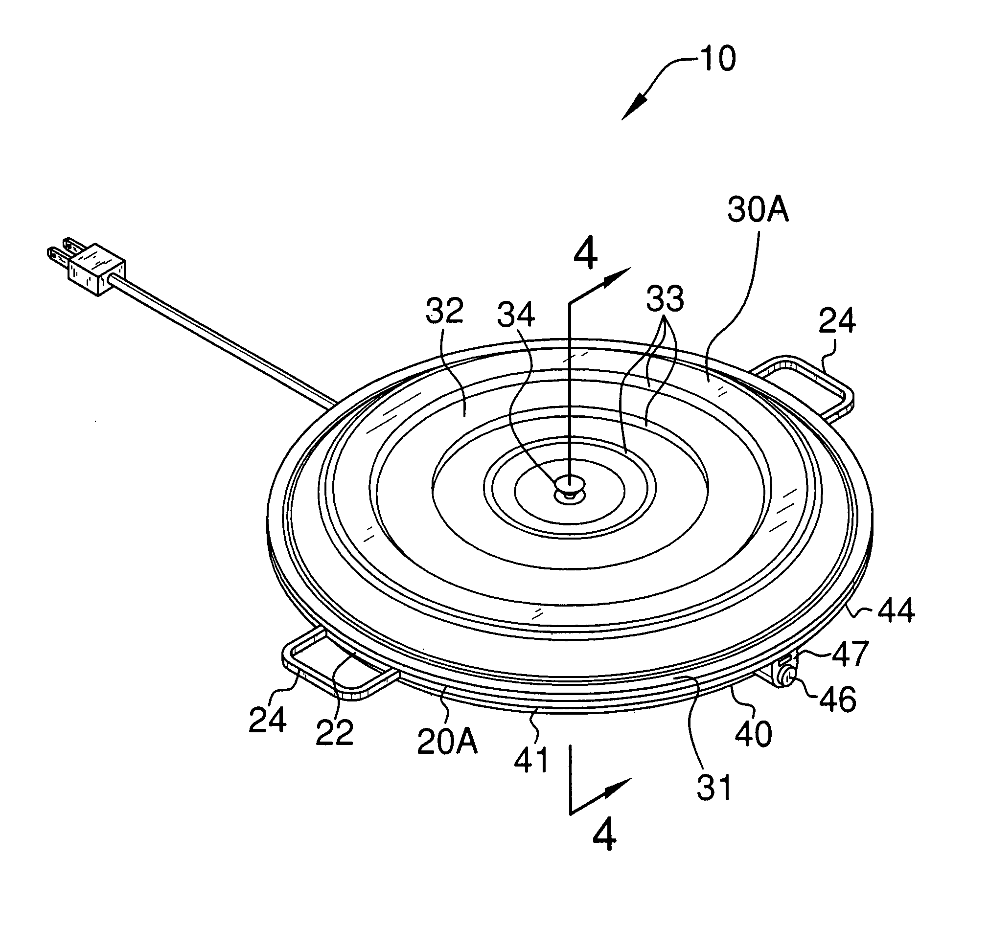
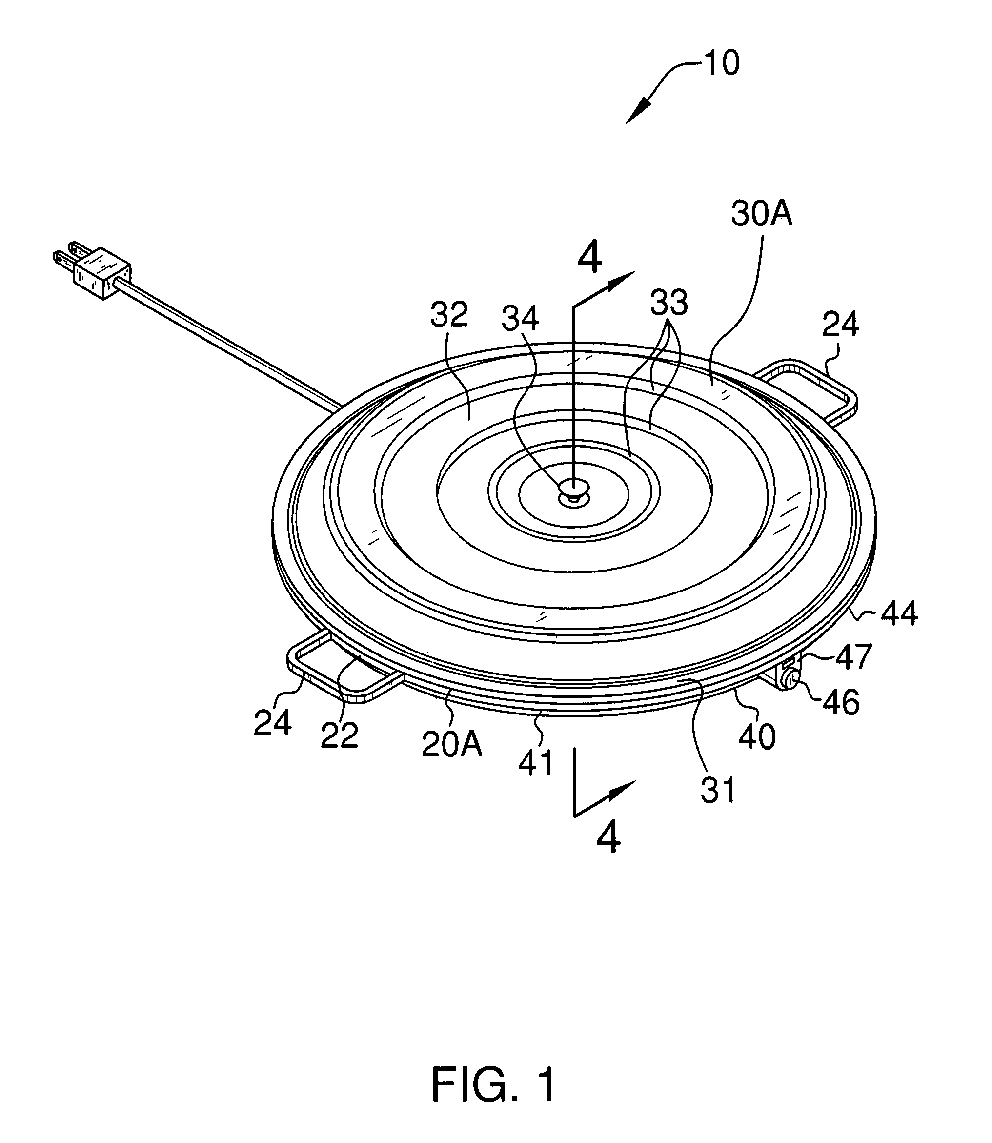
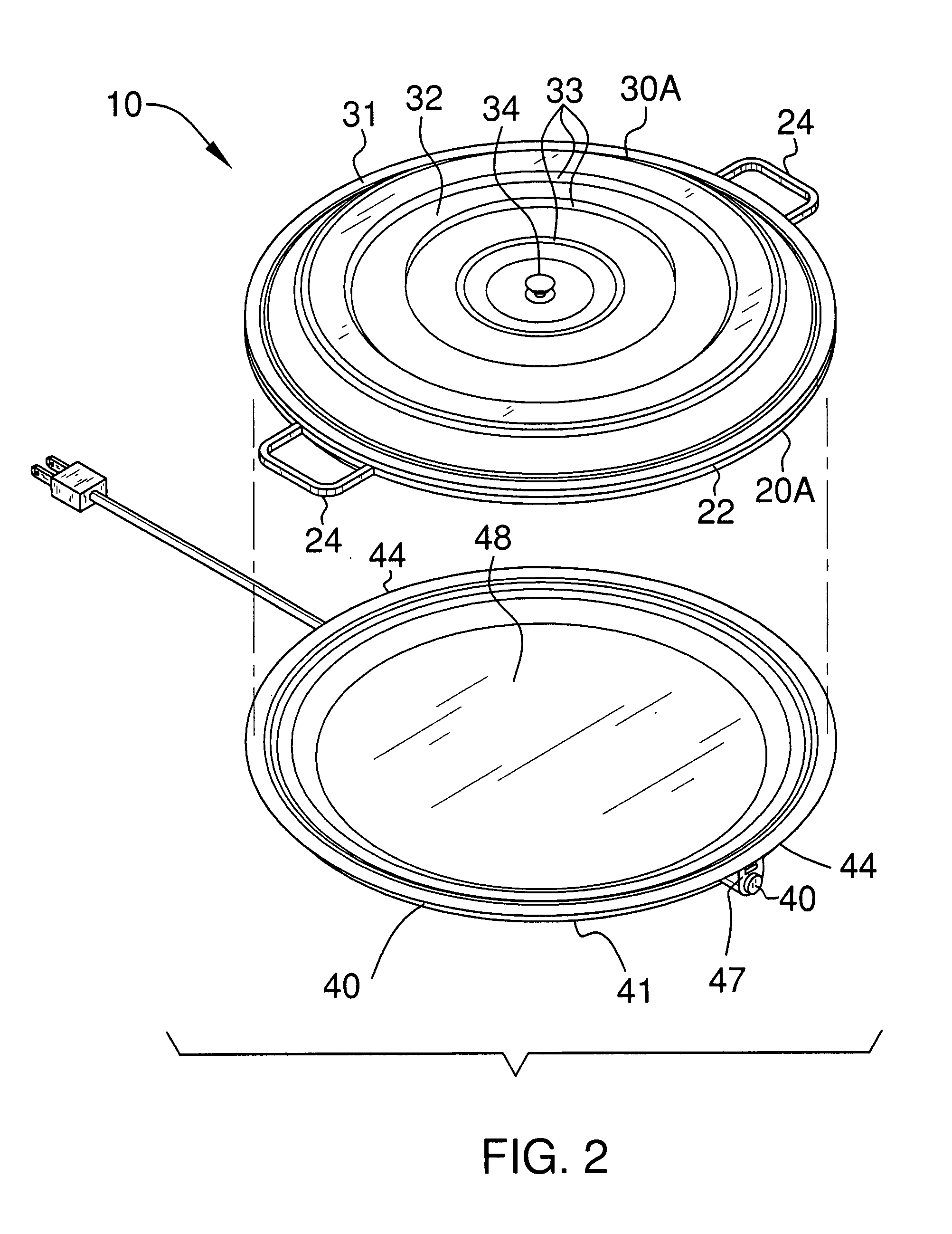
[0030]The device of this invention is referred to generally in FIGS. 1-7 by the reference numeral 10 and is intended to provide a combined food and food-plate warming device. It should be understood that the device 10 may be used to warm many different types of foodstuff and should not be limited in use to only warming left-over food items.

[0031]Referring initially to FIGS. 3, 4 and 7, the device 10 includes a first base 20 plate that has an ...


PUM

PropertyMeasurementUnit
heataaaaaaaaaa
perimeteraaaaaaaaaa
timeaaaaaaaaaa

Abstract

A food and food-plate warming device includes a base plate that has a planar top surface and has an outwardly beveled edge provided with laterally stepped ridges concentrically spaced from the top surface center. A cover plate is positioned on the base plate and has an outer lip that is nested on one of the stepped ridges. Handles are conjoined to the outer lip for receiving at least four contiguous metacarpals therethrough. A mechanism is included for heating the base plate top surface such that the food and food-plate interfitted between the base plate and the cover plate can be heated. The heating mechanism includes a heating element intercalated between the top and bottom surfaces of the first base plate. An automatic shut off switch is coupled to the heating element for interrupting power to the heating element when an interior temperature of the device reaches a maximum threshold temperature.

Description

CROSS REFERENCE TO RELATED APPLICATIONS[0001]Not Applicable.STATEMENT REGARDING FEDERALLY SPONSORED RESEARCH OR DEVELOPMENT[0002]Not Applicable.REFERENCE TO A MICROFICHE APPENDIX[0003]Not Applicable.BACKGROUND OF THE INVENTION[0004]1. Technical Field[0005]This invention relates to warming devices and, more particularly, to a combined food and food-plate warming device.[0006]2. Prior Art[0007]In the interest of saving money and conserving food, many persons will reheat food that was prepared one or two days prior to the event. This is especially true among the elderly, who tend to be on a much more limited budget than those who have a steady working income. In order to properly heat one's food the use of a conventional oven, a toaster oven or a microwave is required. The drawback of using a conventional oven is the fact that the interior volume thereof is so extensive that is becomes counter productive to heat a single plate of food therein. Conventional ovens also consume a lot of e...

Claims


Application Information

Patent Timeline
Patent Type & Authority Patents(United States)
IPC IPC(8): F27B11/00A47J39/00
CPCA47J36/2483
Inventor THOMPSON, JENNIFER J.
Owner THOMPSON JENNIFER J
Why Eureka
Try Eureka