High thermal efficiency electric switch and method for interrupting electric current

a high-efficiency, electric switch technology, applied in the direction of electric switches, electrical equipment, contact engagements, etc., can solve the problems of electrical installations that are not completely or partially destroyed, breakdowns and/or complete or partial destruction of electrical installations, and damage to people, so as to improve energy efficiency, efficient quench the arc, and improve the effect of thermal features

Active Publication Date: 2018-01-18
GORLAN TEAM S L U
View PDF3 Cites 0 Cited by
  • Summary
  • Abstract
  • Description
  • Claims
  • Application Information

AI Technical Summary

Benefits of technology

[0078]An additional advantage of the invention is that the desired number of breaker elements can be arranged in series to most efficiently quench the arc, because the number of breaker elements for the transient state does not jeopardize the energy efficiency of the switch in the permanent state.
[0080]In the transient state: by optimizing the poles for interrupting current, the size of the switch is reduced, substantially reducing the use of copper, aluminum, silver, gold, etc. which has an enormous environmental impact and therefore reduces the cost of the switch. Interruption conditions can further be improved, even producing a higher interrupting power.
[0081]In the permanent state: optimizing the connection of the internal contacts of the switch to increase energy efficiency, achieving better thermal features and lowering the working temperature and in turn energy losses of the switch.
[0082]The present invention achieves an enormous improvement of the environmental impact. To get an idea of the impact generated by the present invention, a 2-pole switch from the current state of the art and having similar interruption features has energy losses of 6 W / h due to the configuration in series that has to be formed between its contacts. The estimation that the switch is in service 9 hours a day on average represents an energy loss of 54 W / day, and therefore 19.71 kW / year.
[0083]The present invention reduce losses in switches by 66% in the best case according to the theoretical data analyzed (see table below), totally 2 W / h and entailing yearly savings of 13.14 kW / year, which contribute to reducing losses in the transmission of electrical energy, therefore meeting the demanding objectives established by the European Union for the year 2020: reduce energy consumption by 20%, reduce greenhouse gas emissions by 20% and increase the use of renewable energies by 20%.ConsumptionConsumptionConsumptionof a 2-poleof 30,000Equivalentof a 2-poleswitchswitches soldin tons ofswitch (W)(Kw / year)(Kw / year)CO2Known619.71591.300251.07switchSwitch of26.57197.10083.69theinventionLoss413.14394.200167.38reduction% savings66%66%66%66%

Problems solved by technology

Electric arcs or voltaic arcs formed in electrical circuits are known to cause many problems today because the heat energy produced during an electric arc is highly destructive.
Some of these problems are: deterioration of the switch material, breakdowns and / or complete or partial destruction of electrical installations, including damage to people caused by burns or other types of injuries.
However, though there are currently electric breaker switches combining some of the techniques mentioned above, i.e., spark quenching chamber with magnetic or pneumatic blowout, radial rather than linear separation of contacts, etc., said switches today still do not satisfactorily solve their main function of quenching electric arcs, because the quenching time is still too long and material is still subject to deterioration, particularly in very demanding applications such as high power direct current interruption.
Furthermore, techniques known for quenching arcs generally involve an increase in the volume of the switches due to the volume of air needed between contacts.
Operation of switch breaker mechanisms usually involves some type of impact between parts, which in the long-term causes deterioration due to material wear which can lead to destruction of the switch.
However, there are also drawbacks associated with said connection in series:It is necessary to increase the size of the switch to house more poles.A larger amount of conductive material is used.The working temperature increases as there are 2, 3 or more poles connected in series withstanding the same current as one pole.Energy consumption increases because each pole is equivalent to a resistance and since the poles are grouped in series, an equivalent final resistance equal to the sum of all resistances is obtained.
As can be seen, the advantages of connecting the poles in series contribute to optimizing the dynamic state, i.e., when the electric arc is interrupted; however, it involves an enormous drawback in the idle or permanent state they are in for 95% of their service life, which entails greater energy consumption.
Materials that are good electrical conductors are generally used, but those materials are soft and poorly arc resistant, so they require external coatings or treatments to improve their arc resistance and increase their melting temperature.
This increases manufacturing costs, and the chosen material is never optimal for both the transient and permanent states.

Method used


Image

  • High thermal efficiency electric switch and method for interrupting  electric current
  • High thermal efficiency electric switch and method for interrupting  electric current
  • High thermal efficiency electric switch and method for interrupting  electric current

Examples


Embodiment Construction

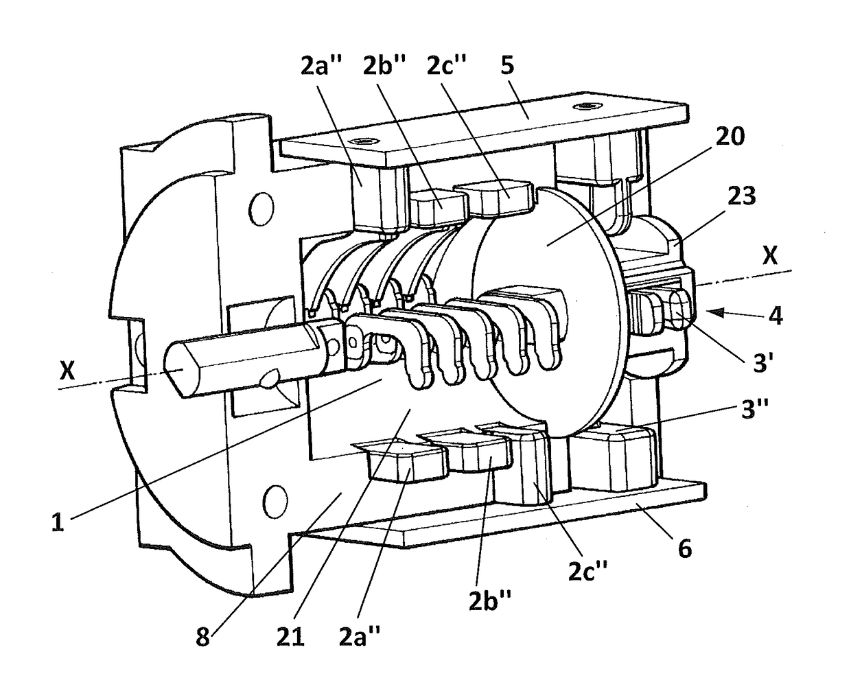
[0039]The drawbacks described above are solved by means of the present invention, providing an electric breaker switch which rapidly and effectively interrupts the electric arc, in a small space, while at the same time having low power losses due to heating during the electrical conduction permanent state.

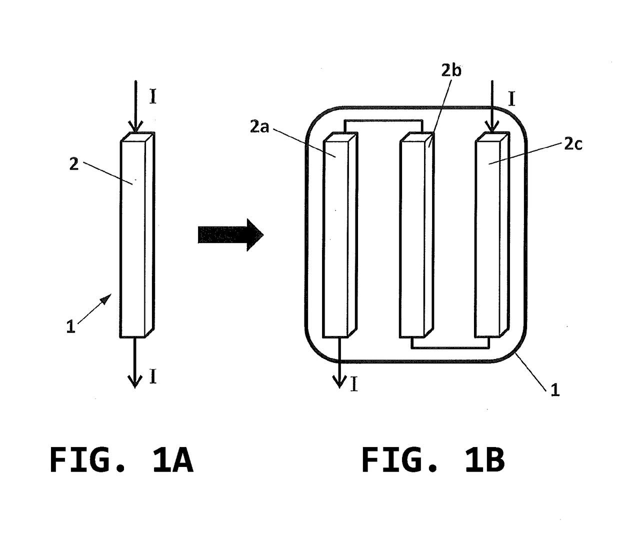
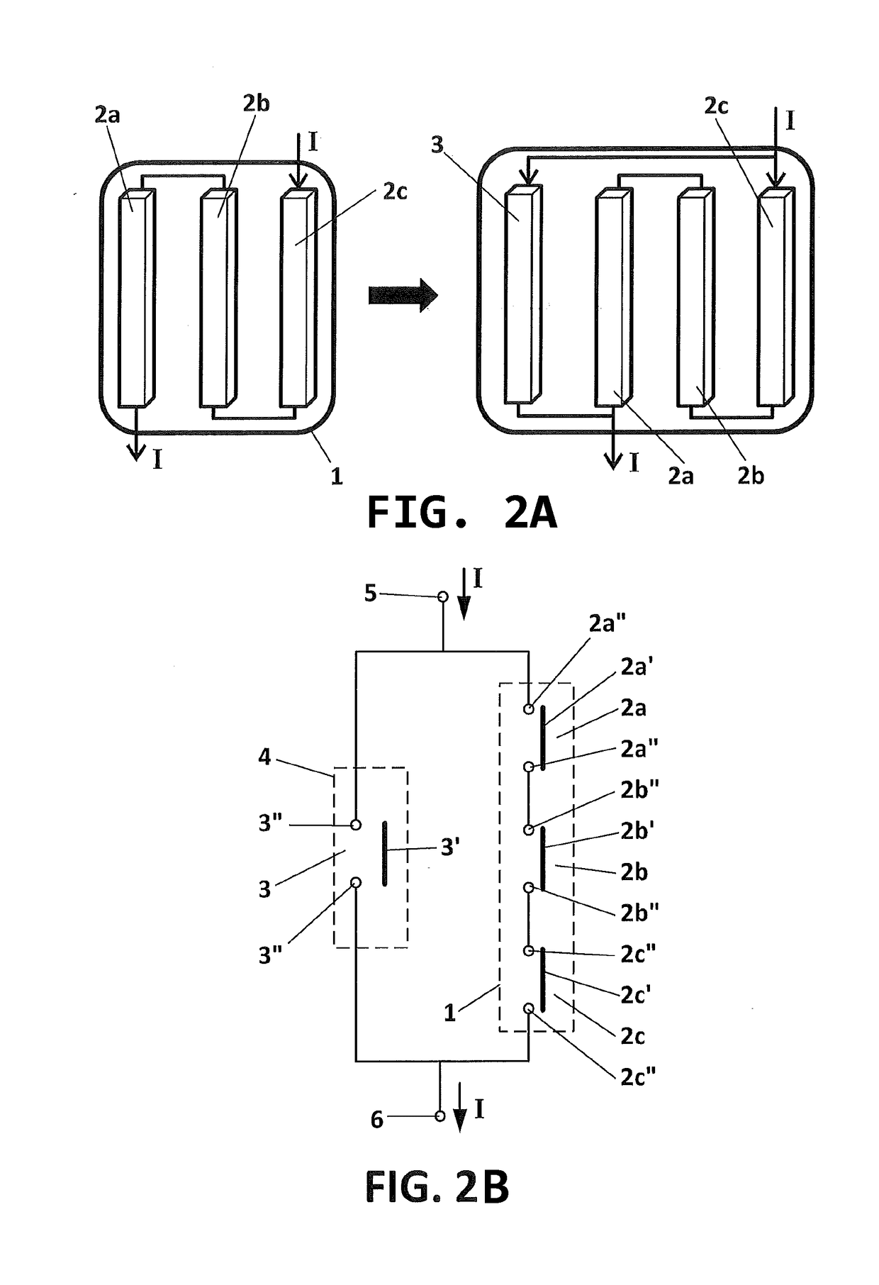
[0040]The invention is based on providing a switching device that behaves differently during transient electric current interruption and connecting periods and in the electrical conduction permanent state once the transient period has concluded, such that in the transient period the current is made to flow through several electric interruption points connected in series to therefore aid in quenching arcs in switch closing and opening operations, whereas in permanent operating periods the current is made to flow through a breaker element having a low electrical resistance so that power losses are reduced.

[0041]To that end, a first aspect of the invention relates to an electric switc...


PUM


Abstract

An electric switch includes a first and a second connection terminal for connecting the switch to an external circuit; a first switch assembly, which includes two or more electric breaker elements connected in series to one another and to the first and the second connection terminal; a second switch assembly, which includes at least one delayed electric breaker element connected in parallel to the first switch assembly. A moving actuator is made of insulating material and is associated with the first and the second switch assembly to open or close them. The moving actuator is movable between a closed switch position in which electrical continuity is established between the first and the second connection terminal, and an open position in which current flow between said terminals is prevented.

Description

CROSS-REFERENCE TO RELATED APPLICATIONS[0001]This application is a Continuation of U.S. application Ser. No. 15 / 125,129, filed on Sep. 9, 2016 as the U.S. National Phase under 35 U.S.C. §371 of International Application PCT / ES2014 / 070831, filed Nov. 7, 2014. The disclosure of the above-described application are hereby incorporated by reference in its entirety.OBJECT OF THE INVENTION[0002]The present invention is comprised in the field of electric switches and / or disconnect switches, particularly adapted for quenching the electric arc formed when the contacts thereof open and close.[0003]One object of the present invention is to provide a small-sized electric breaker switch that rapidly and effectively extinguishes electric arcs formed in an electrical circuit during transient current interruption and closing operations.[0004]Another additional object of the present invention is to provide a high thermal efficiency electric, i.e. more energy-efficient, breaker switch because it reduc...

Claims


Application Information

Patent Timeline
Patent Type & Authority Applications(United States)
IPC IPC(8): H01H9/40H01H15/10H01H1/36H01H9/02H01H19/56H01H15/20
CPCH01H15/10H01H9/02H01H9/40H01H19/56H01H15/20H01H1/36
Inventor ANDALUZ SORLI, JOSE OSCAR
Owner GORLAN TEAM S L U
Why Eureka
Try Eureka