LED driver, lighting device and LED based lighting application

a technology of led driver and led light, applied in the direction of transmission, lighting and heating equipment, electrical equipment, etc., can solve problems such as difficulty in modification or adjustment, and achieve the effect of facilitating communication

Active Publication Date: 2016-05-31
ELDOLAB HLDG
View PDF11 Cites 0 Cited by
  • Summary
  • Abstract
  • Description
  • Claims
  • Application Information

AI Technical Summary

Benefits of technology

[0032]In an embodiment, the application terminal is further applied to power the lighting device. Such powering can be limited to a powering of the control unit of the lighting device or may also include the powering of a sensor or LED fixture that is part of the lighting device. In such embodiment, a buffer such as a capacitance can be provided at the application terminal or at the i / o terminal. In such an embodiment, the power as supplied to the sensor or LED fixture may temporarily be interrupted during the transmission of the polling signal and the receipt of the first control signal. In case the lighting device comprises the LED fixture, the output power as provided by the power converter of the LED driver can thus be provided to the LED fixture via the application terminal. In such arrangement (which is explained in more detail in e.g. FIG. 6), both the powering of the LED fixture and any communication to and / or from the LED driver can take place over the same electric wiring. As illustrated in e.g. FIG. 6, a two-wire connection between the LED driver and the LED fixture is thus sufficient to both power the LED fixture and, as discussed above, among others, facilitate in providing configuration or control data to the LED driver.
[0036]Compared to conventional LED drivers for an LED fixture, the characteristics of the LED driver according to the invention can thus be adjusted depending on the type of LED fixture to be powered whereas the characteristics of know power supplies that are used in lighting networks, in general, have predetermined characteristics. As such, a particular type of LED fixture can influence the behavior of the LED driver when connected to it. As such, for a driver manufacturer, it may be sufficient to support only one type of LED driver like the LED driver according to the present invention (thus facilitating e.g. stock management, maintenance or minimizing design effort), since such driver can be applied in a comparatively large number of different applications due to the configuration flexibility offered by the LED driver.
[0050]In an embodiment, the LED based lighting application according to the present invention e.g. enables the adjustment of a configuration parameter of the LED driver using a control signal received at the application terminal of the LED driver. In accordance with the invention, the control signal originates from a lighting device, such lighting device e.g. being an LED fixture or a sensor such as an ambient or occupancy sensor. Such an approach of adjusting configuration parameters facilitates the configuration or re-configuration of a LED driver that is used in a network environment such as a DALI network.
[0054]As will be explained in more detail below, introducing such a delay, enables a faster communication between the lighting device and the LED driver receiving the first control signal.
[0066]The lighting device according to the invention may further, in an embodiment, comprise a so-called bridge for converting a signal, e.g. received from the sensor, to a suitable format for processing by the control unit. Such a bridge can e.g. comprise an interface such as a USB, DMX or other interface for facilitating the communication between the e.g. a sensor of the lighting device and the control unit.

Problems solved by technology

At present however, LED drivers that are adapted to operate in a communication network as described are often found to have a predetermined characteristic behavior and are as such, difficult to modify or adjust in order to obtain an optimal match with a particular application such as an LED fixture that is to be powered.

Method used


Image

  • LED driver, lighting device and LED based lighting application
  • LED driver, lighting device and LED based lighting application
  • LED driver, lighting device and LED based lighting application

Examples


Embodiment Construction

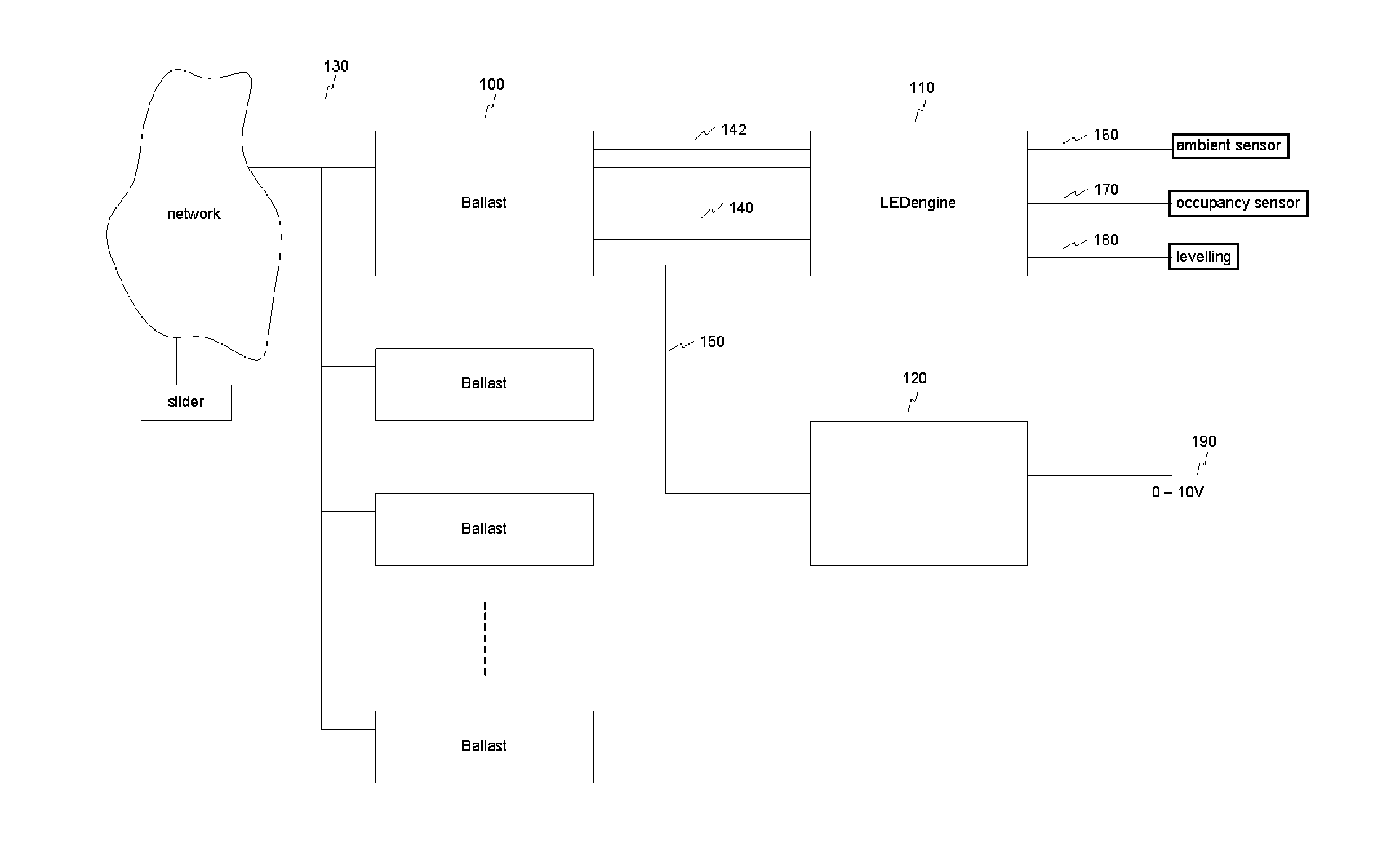
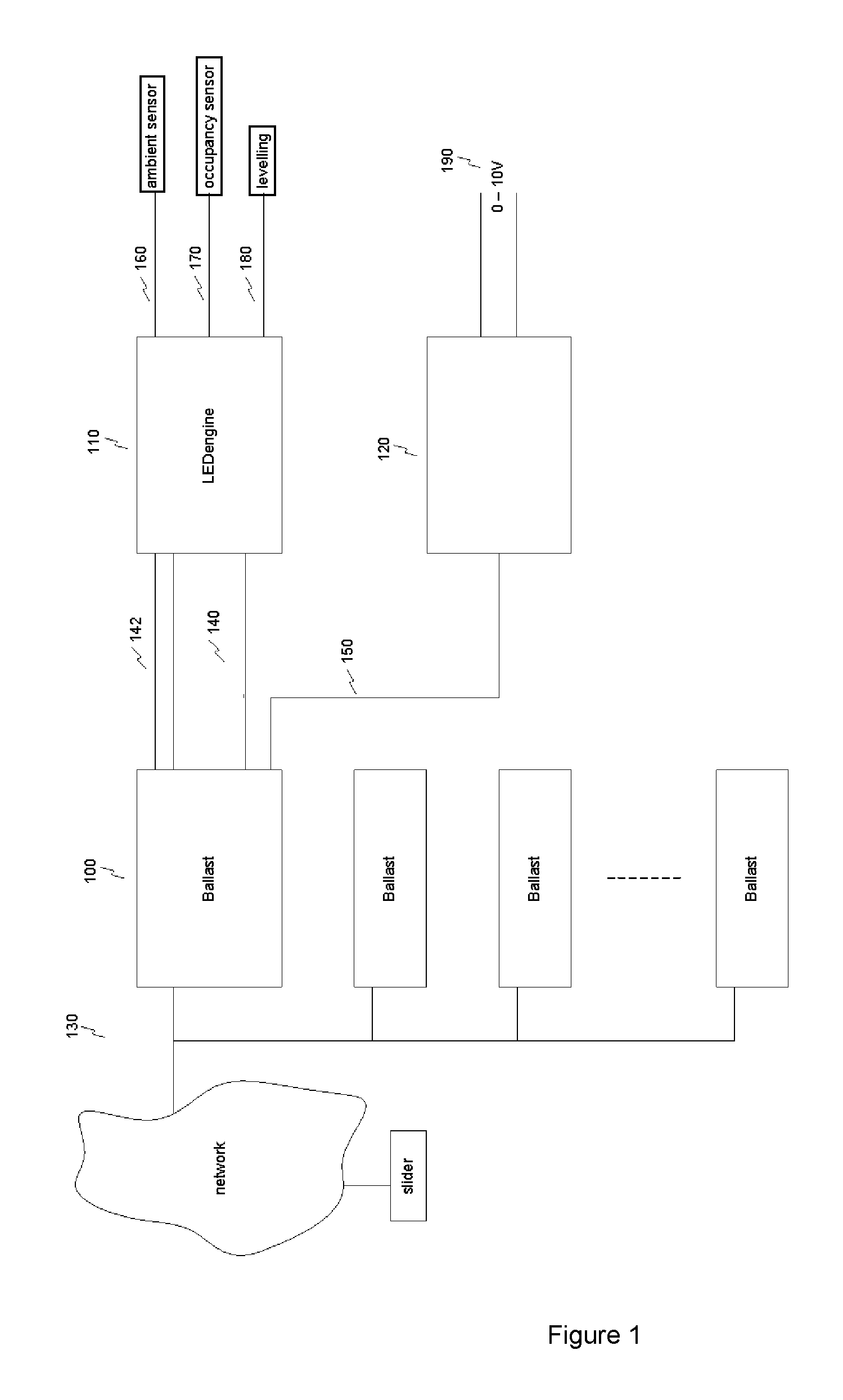
[0076]FIG. 1 schematically depicts a lighting application according to an embodiment of the present invention operating in a network environment. The lighting application as shown comprises a plurality of ballasts / LED drivers or power supplies 100 arranged to power (one or more) LED fixtures 110 (also referred to as LED engines).

[0077]In an embodiment, such an LED fixture can merely comprise one or more LEDs mounted in a fixture or socket or the like. More advanced LED fixtures may further include sensors such as ambient or occupancy sensors or may be adapted for connecting to such sensors, as schematically indicated by lines 160 and 170. Such connections may by either wired or wireless connections.

[0078]The plurality of ballasts 100 is, as can be seen in FIG. 1, connected to a network 130, e.g. using DMX, 0-10V or DALI or alike as a communication protocol. As such, the ballasts each have a network terminal connected to a control unit of the ballast (not shown) for connecting to the...


PUM


Abstract

An LED driver for powering an LED fixture includes a power converter for converting an input power such as a rectified mains supply to an output power for powering the LED fixture; a control unit arranged to control an output characteristic of the power converter; optionally, a network terminal connected to the control unit for connecting the control unit to a network, the control unit being arranged to receive a control signal from the network via the network terminal for controlling the output characteristic; an application terminal connected to the control unit for connecting the control unit to a lighting device; the control unit being arranged to: provide a polling signal to the lighting device; receive, in response to the polling signal, a control signal for controlling the output characteristic.

Description

CROSS-REFERENCE TO RELATED APPLICATIONS[0001]This application is the National Stage of International Application No. PCT / NL2011 / 050887, filed Dec. 22, 2011, which claims the benefit of Netherlands Application No. 2005929, filed Dec. 28, 2010, and of U.S. Provisional Application No. 61 / 427,600, filed Dec. 28, 2010, the contents of all of which are incorporated by reference herein.FIELD OF THE INVENTION[0002]The invention relates to the field of power supplies of LED based lighting applications and more specifically to power supplies adapted for operating in a network environment.BACKGROUND OF THE INVENTION[0003]In general, LED based lighting applications are powered from a lighting grid via a so-called LED driver or ballast. Such an LED driver or ballast can e.g. comprise a Buck or Boost power converter or the like.[0004]LED based lighting applications often comprise a plurality of LED fixture (or LED engine) which can be independently controlled or adjusted by a user (via one or mor...

Claims


Application Information

Patent Timeline
Patent Type & Authority Patents(United States)
IPC IPC(8): H05B41/36H05B37/02H05B33/08H05B44/00
CPCH05B33/0809H05B33/0842H05B37/0254F21V23/003H05B47/18Y02B20/40H05B47/115H05B45/3725H05B47/14H05B45/12H05B47/11F21Y2115/10F21V23/02H04L67/12
Inventor SAES, MARC
Owner ELDOLAB HLDG
Why Eureka
Try Eureka