Three-dimensional interior design system

a three-dimensional interior design and computerized technology, applied in the field of three-dimensional interior design systems, can solve the problems of inability to show objects in the context of a background scene, inability to manipulate objects, and inherent limitations of both cmyvisionTM and visualphileTM systems

Active Publication Date: 2007-10-02
AR DESIGN INNOVATIONS LLC
View PDF9 Cites 247 Cited by
  • Summary
  • Abstract
  • Description
  • Claims
  • Application Information

AI Technical Summary

Benefits of technology

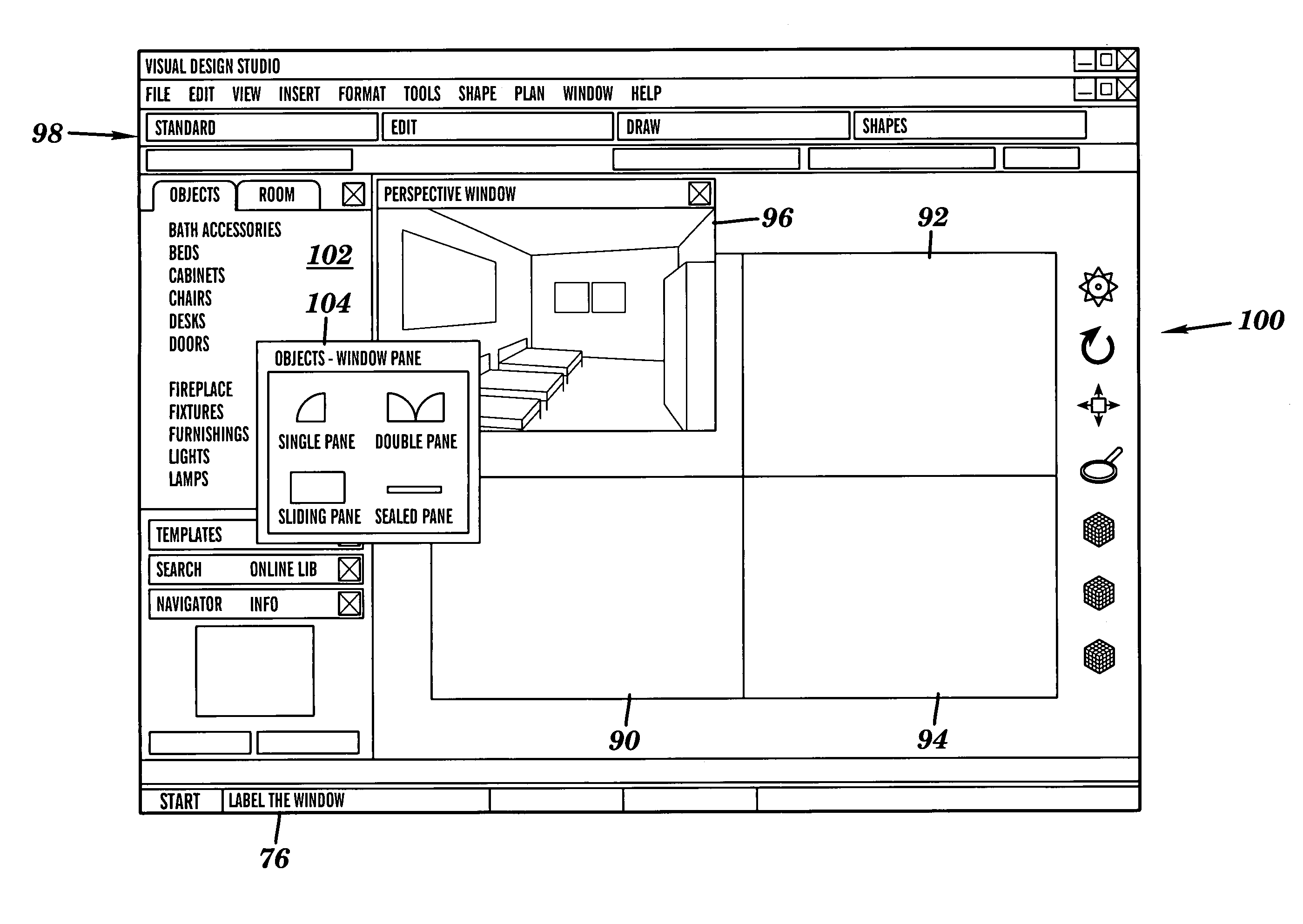
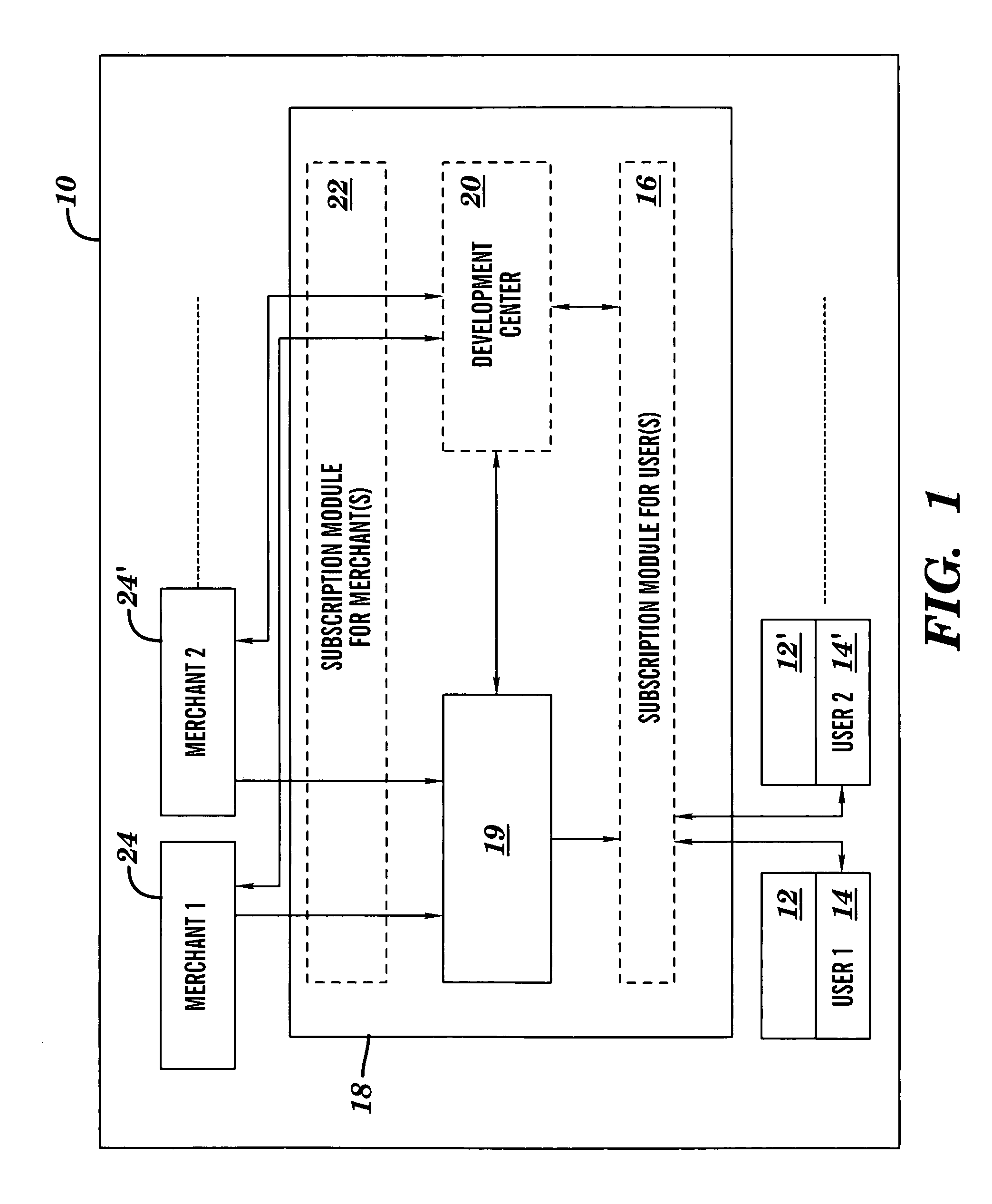
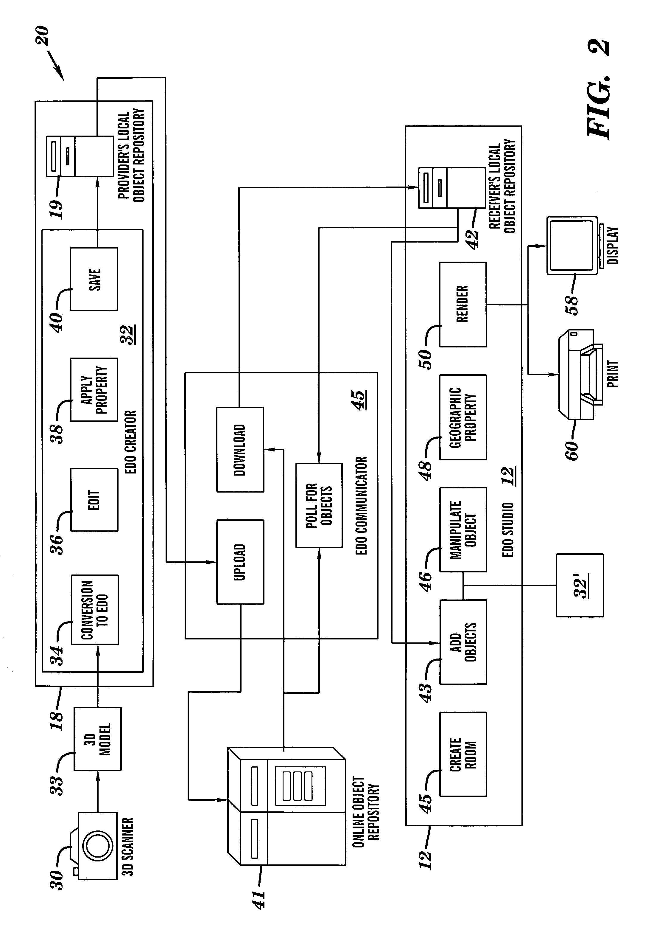
[0022]Another aspect of the present invention includes a method in a client-server computing environment for generating and rendering a photorealistic three-dimensional (3D) perspective view of a 3D object selectively positioned within a 3D scene. The method includes loading a plurality of 3D objects onto a server, at least one of the 3D objects representing a product; loading product ordering information for each product onto the server; loading a client application configured for scene editing and rendering, including a graphical user interface (GUI), onto the server; combining the plurality of 3D objects, with their integrated product ordering information, to form integrated 3D objects; converting the integrated 3D objects into a format usable by the client application; storing the integrated formatted 3D objects in a server library; communicably coupling the server to a client; and transmitting the client application to the client. The method also includes transmitting selected ones of plurality of 3D objects from the server library to a client library; automatically updating the plurality of 3D objects in the server library, including their associated product ordering information; and automatically transmitting updates for the selected ones of 3D objects in the server library, to the client; so that a user may manipulate the selected 3D objects with the client application to generate a 3D scene at the client.

Problems solved by technology

This system generates furniture images in 2D as opposed to 3D, does not enable them to be shown in context of a background scene (e.g., a particular room), and does not enable them to be manipulated, e.g., for scaling, rotation and particular placement within the background scenes.
However, there exist inherent limitations to both the cMyVision™ and VisualPhile™ systems, which may be severe when applied to professional interior design, relative to their use of digital photographs.
Moreover, because the furniture images are only photographs, and not 3D models, it is generally not possible to map fabrics on them.
In other words, while Photo Home Interiors™ does allow furniture objects to be shown as an overlay on top of room photographs, it lacks the capability of rendering furniture objects placed onto floor plans in photographically-derived scenes.
Therefore, this program does not allow wall and floor coverings to be displayed in the proper perspective.
With this system, it is not possible to evaluate furniture objects of specific dimensions as to scale.
While this system may overcome some of the disadvantages of the prior art, it is not without drawbacks, not the least of which is the time lag associated with uploading the “frame” of the scene, waiting for the server to render the 3D composite, and downloading a relatively large file or array of files.
Moreover, additional changes made after such rendering, such as moving objects within the scene, presumably cannot be effected at the client computer.

Method used


Image

  • Three-dimensional interior design system
  • Three-dimensional interior design system
  • Three-dimensional interior design system

Examples


Embodiment Construction

[0035]In the following detailed description, reference is made to the accompanying drawings that form a part hereof, and in which is shown by way of illustration, specific embodiments in which the invention may be practiced. These embodiments are described in sufficient detail to enable those skilled in the art to practice the invention, and it is to be understood that other embodiments may be utilized. It is also to be understood that structural, procedural and system changes may be made without departing from the spirit and scope of the present invention. The following detailed description is, therefore, not to be taken in a limiting sense, and the scope of the present invention is defined by the appended claims and their equivalents. For clarity of exposition, like features shown in the accompanying drawings shall be indicated with like reference numerals and similar features as shown in alternate embodiments in the drawings shall be indicated with similar reference numerals.

[003...


PUM


Abstract

A system and method in a client-server computing environment is provided for generating and rendering a photorealistic three-dimensional (3D) perspective view of a 3D object selectively positioned within a 3D scene. A client is configured for communicably accessing a server, and includes a client application configured for scene editing and rendering, using a graphical user interface (GUI). The 3D scene may be selectively displayed in a plurality of views, and a 3D object may be retrieved from the server and imported into the 3D scene to generate a composite. The 3D object may also be manipulated within the composite for placement and orientation. A 3D image of the composite may then be rendered at the client and selectively reconfigured in real time. Luminosity characteristics may be applied to the 3D image; followed by rendering a photorealistic 3D view of the composite image.

Description

BACKGROUND[0001]1. Technical Field[0002]This invention relates to computerized three-dimensional modeling systems, and more particularly, to a software application configured to reside on a client computer, which is capable of manipulating 3-D object representations in-situ with a user-selected or user-generated interior design scene, and rendering photographic quality perspective images of the composite scene.[0003]2. Background Information[0004]Throughout this application, various publications, patents and published patent applications are referred to by an identifying citation. The disclosures of the publications, patents and published patent applications referenced in this application are hereby incorporated by reference into the present disclosure.[0005]Many systems have been devised to provide various design and modeling functionality. For example, U.S. Pat. No. 5,255,352 to Falk for MAPPING OF TWO-DIMENSIONAL SURFACE DETAIL ON THREE-DIMENSIONAL SURFACES concerns a system and ...

Claims


Application Information

Patent Timeline
Patent Type & Authority Patents(United States)
IPC IPC(8): G06K9/00G06FG06F3/00G06F17/50G06T17/40
CPCG06F17/5004G06T19/20G06F2217/04G06T2219/2016G06T2210/04G06T2219/2004G06T2200/24G06F2111/02G06F30/13G06Q30/0643G06Q10/103G06Q30/0277G06Q30/0621G06Q50/04G06Q30/01G06F18/00
Inventor MACINNES, CATHRYNPEARLSTEIN, GERALD
Owner AR DESIGN INNOVATIONS LLC
Why Eureka
Try Eureka