
Spacial deblocking method using limited edge differences only to linearly correct blocking artifact

Inactive Publication Date: 2007-10-02
REDROCK SEMICON
View PDF22 Cites 24 Cited by
  • Summary
  • Abstract
  • Description
  • Claims
  • Application Information

AI Technical Summary

Problems solved by technology

These compression techniques are lossy techniques, since some of the picture information is discarded to increase the compression ratio.
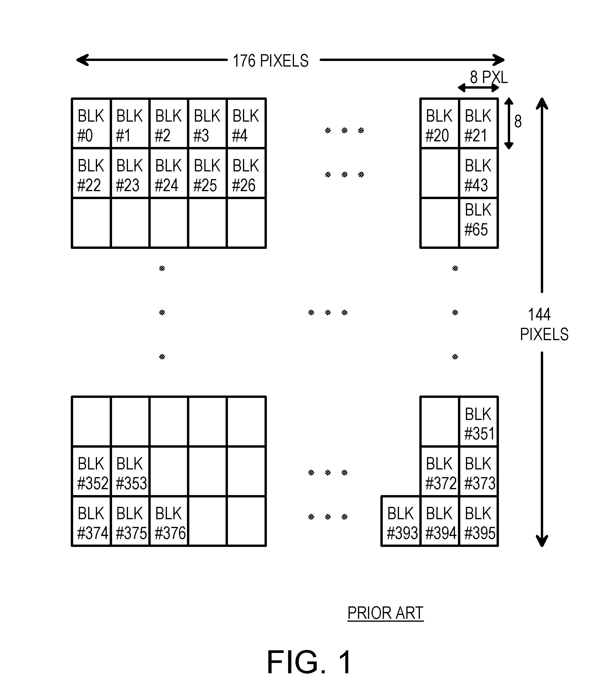
Since each bock is compressed separately from other blocks, there can be noticeable discontinuities at block edges.
Large pixel differences may be caused by a real edge in the image, while smaller pixel differences are more likely caused by compression noise.
A large amount of computational work is required for each pair of edge pixels that are smoothed.

Method used


Image

  • Spacial deblocking method using limited edge differences only to linearly correct blocking artifact
  • Spacial deblocking method using limited edge differences only to linearly correct blocking artifact
  • Spacial deblocking method using limited edge differences only to linearly correct blocking artifact

Examples


Embodiment Construction

[0030]The present invention relates to an improvement in de-blocking filters. The following description is presented to enable one of ordinary skill in the art to make and use the invention as provided in the context of a particular application and its requirements. Various modifications to the preferred embodiment will be apparent to those with skill in the art, and the general principles defined herein may be applied to other embodiments. Therefore, the present invention is not intended to be limited to the particular embodiments shown and described, but is to be accorded the widest scope consistent with the principles and novel features herein disclosed.

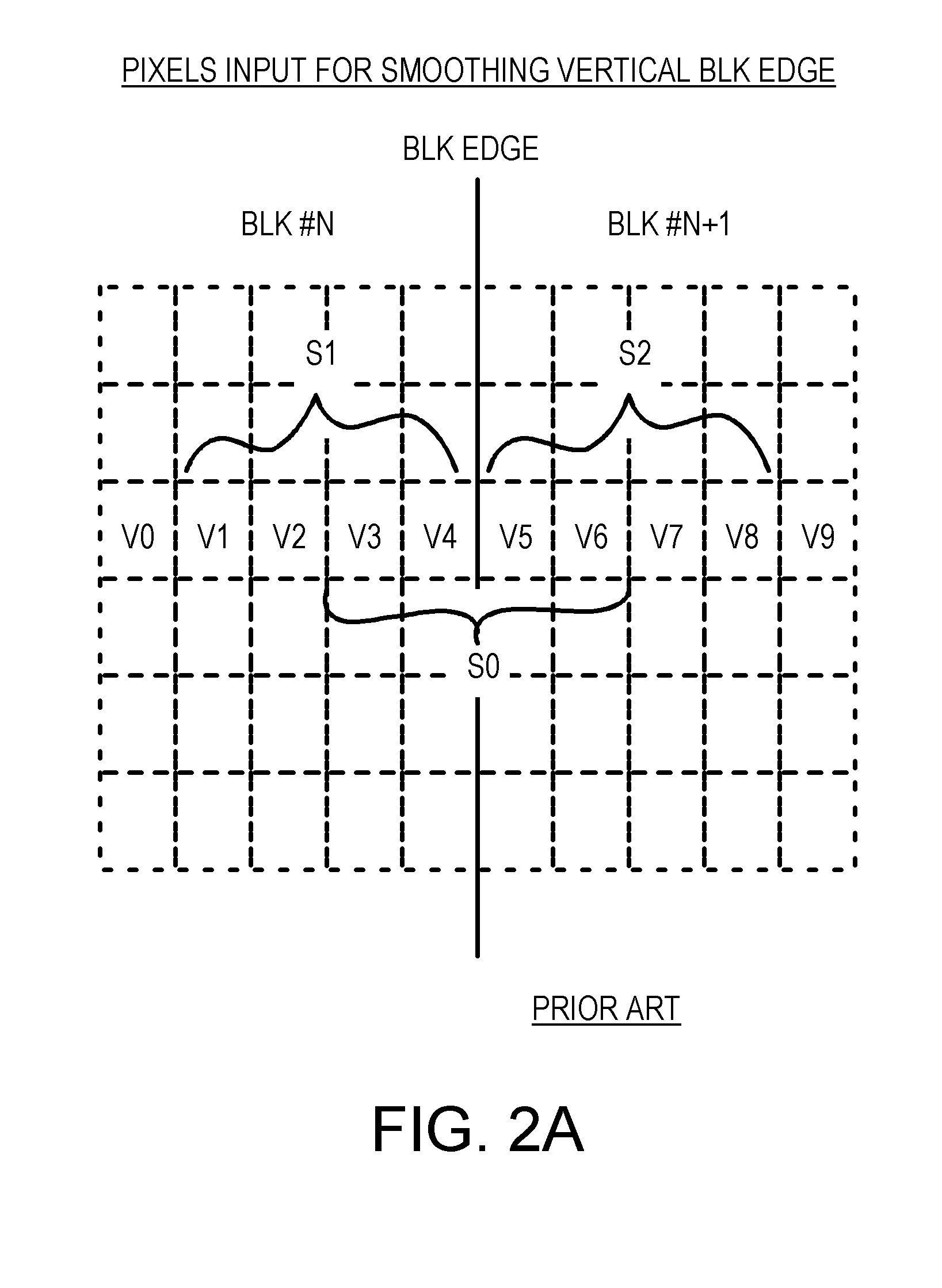
[0031]The inventor has realized that much of the computational work of the prior-art de-blocking method is consumed by the vector multiplies. A large number of pixels are input early in the de-blocking process to generate frequency components for smoothing.

[0032]The inventor realizes that computational work can be reduced by input...


PUM


Abstract

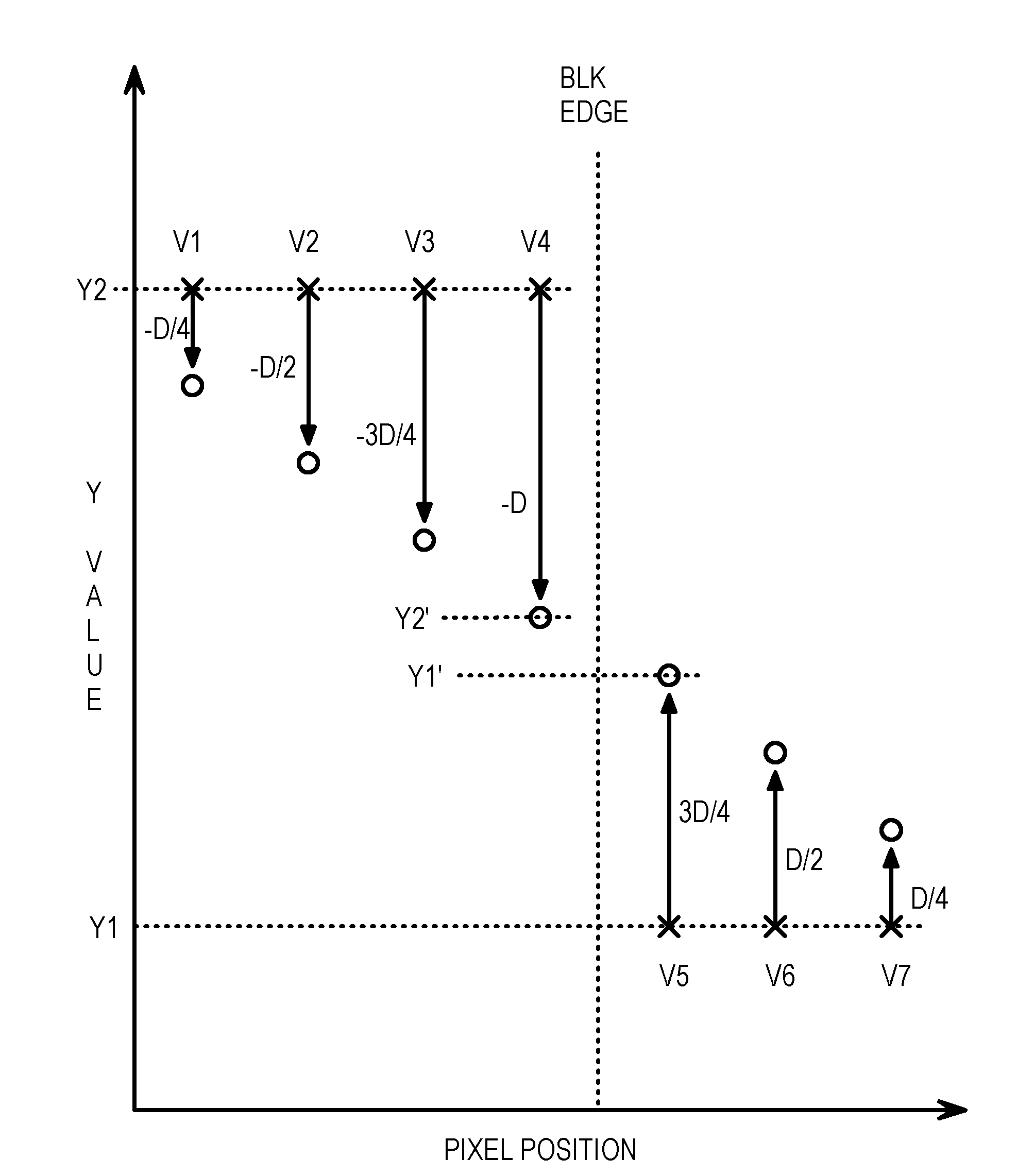
A de-blocking method smoothes pixels along a row or column that crosses a block boundary. Smoothing is performed to remove quantization or compression artifacts that appear on block edges when pixels in adjacent blocks are separately compressed. A maximum-allowed edge-pixel difference is generated from the quantization parameter QP. For each edge-crossing row or column, an edge difference is generated as half the difference between adjacent edge pixels in two blocks. This edge difference is compared to the maximum-allowed edge-pixel difference. When the edge difference is larger than the maximum-allowed edge-pixel difference, then the difference is limited to the maximum-allowed edge-pixel difference, since the pixel difference may be a real edge in the image. The limited or edge difference is then added or subtracted in decreasing amounts for several pixels in the row or column near the edge, smoothing the edge difference across several pixels, such as seven pixels.

Description

BACKGROUND OF INVENTION[0001]This invention relates to video compression, and more particularly for spatial de-blocking methods.[0002]Video data can greatly enhance the quality of a computing experience. The consumer use of the Internet took off once graphics was linked to earlier text-based web pages. Portable consumer devices such as cell phones and personal digital assistant (PDA's) are being equipped with small cameras to allow for capture of still or even video pictures. Efficient transmission of captured images over limited-bandwidth links requires some sort of compression of the images.[0003]A number of video-compression techniques are known. Compression standards, such as those developed by the motion-picture-experts group (MPEG), have been widely adopted. These compression techniques are lossy techniques, since some of the picture information is discarded to increase the compression ratio. However, compression ratios of 99% or more have been achieved with minimal noticeable...

Claims


Application Information

Patent Timeline
IPC IPC(8): G06K9/40
CPCH04N19/86H04N19/42
Inventor LIN, TAO
Owner REDROCK SEMICON
Learn More