Image data processing method, and image data processing circuit

a technology of image data and processing circuit, which is applied in the direction of static indicating devices, instruments, television systems, etc., can solve the problems of inability to rapidly change images, the size of image memory, and the liquid crystal used in liquid crystal panels, so as to reduce the size of the image memory forming the delay unit

Active Publication Date: 2008-07-22
TRIVALE TECH
View PDF27 Cites 23 Cited by
  • Summary
  • Abstract
  • Description
  • Claims
  • Application Information

AI Technical Summary

Benefits of technology

[0017]According to the present invention, the data are compressed before being delayed, so the size of the image memory forming the delay unit can be reduced, and changes in the image data-can be detected accurately.

Problems solved by technology

However, the liquid crystals used in liquid crystal panels have the disadvantage of being unable to handle rapidly changing images, because the transmittance varies according to a cumulative response effect.
The number of pixels displayed on liquid crystal panels is increasing, due especially to increased screen size and higher definition in recent years, and the amount of image data per frame is increasing accordingly, so a need has arisen to increase the size of the image memory used for the delay; this increase in the size of the image memory raises the cost of the display device.
A problem is that when the image data stored in the frame memory are reduced by a simple rule such as removing every other pixel vertically and horizontally, as in document 2 above, amounts of temporal change in the image data reconstructed by replacing the eliminated pixel data with adjacent pixel data may not be calculated correctly, in which case, since the amount of change used in compensation of the image data is erroneous, the compensation of the image data is not performed correctly, and the effectiveness with which the response speed of the liquid crystal display device is improved is reduced.

Method used


Image

  • Image data processing method, and image data processing circuit
  • Image data processing method, and image data processing circuit
  • Image data processing method, and image data processing circuit

Examples


first embodiment

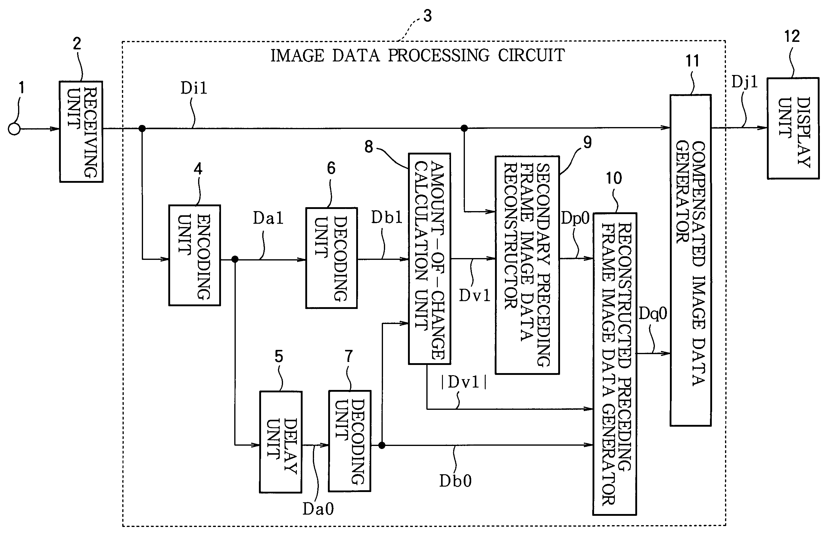
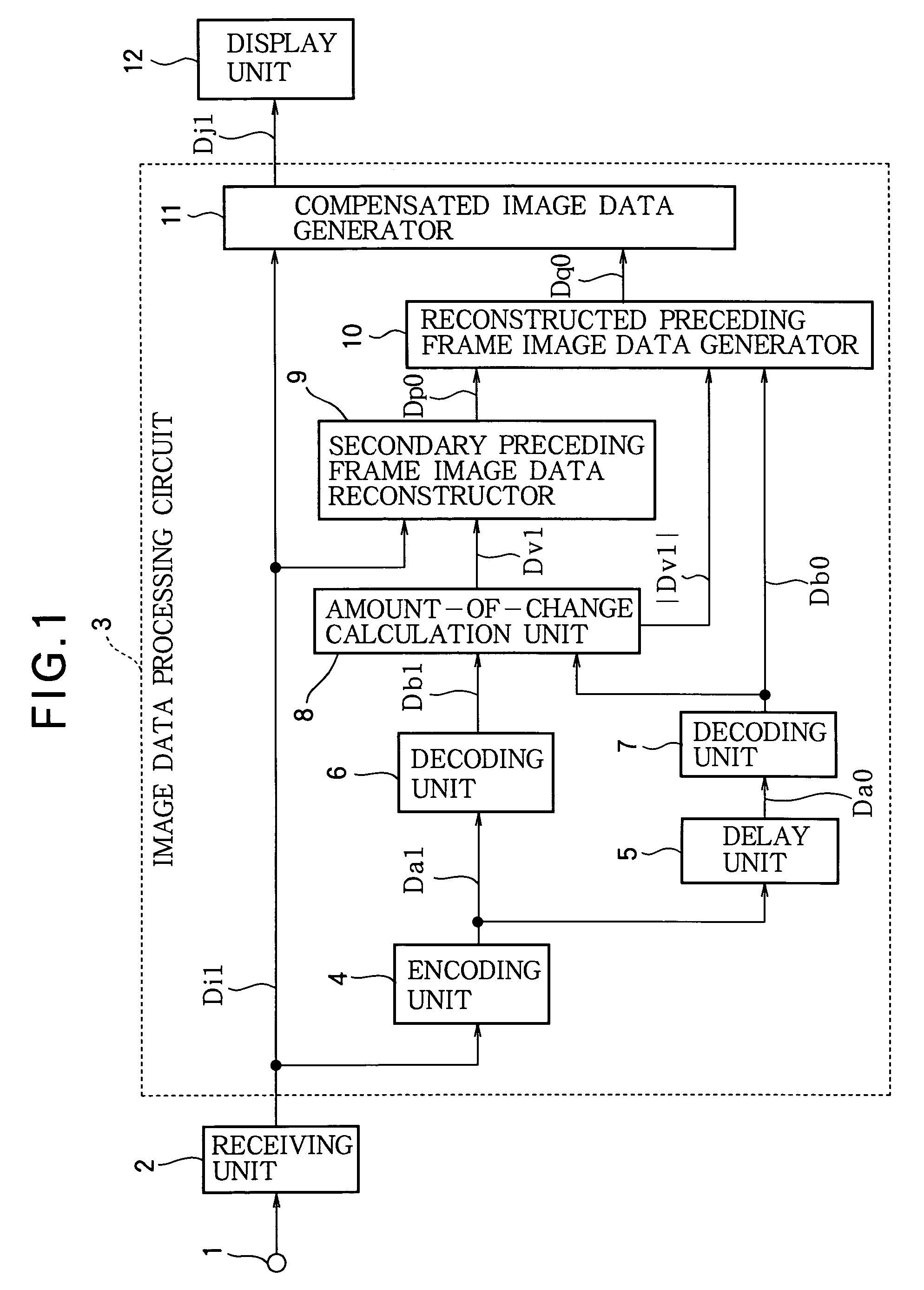
[0043]FIG. 1 is a block diagram showing the configuration of a liquid crystal display driving device according to a first embodiment of the present invention;

[0044]The input terminal 1 is a terminal through which an image signal is input to display an image on a liquid crystal display device. A receiving unit 2 performs tuning, demodulation, and other processing of the image signal received at the input terminal 1 and thereby successively outputs image data representing a one-frame portion of the present image, that is, the image data Di1 of the present frame (the current frame). The image data Di1 of the current frame, which have not undergone processing such as encoding in the processing circuit, will also be referred to as the original current frame image data.

[0045]The image data processing circuit 3 comprises an encoding unit 4, a delay unit 5, decoding units 6 and 7, an amount-of-change calculation unit 8, a secondary preceding frame image data reconstructor 9, a reconstructed...

second embodiment

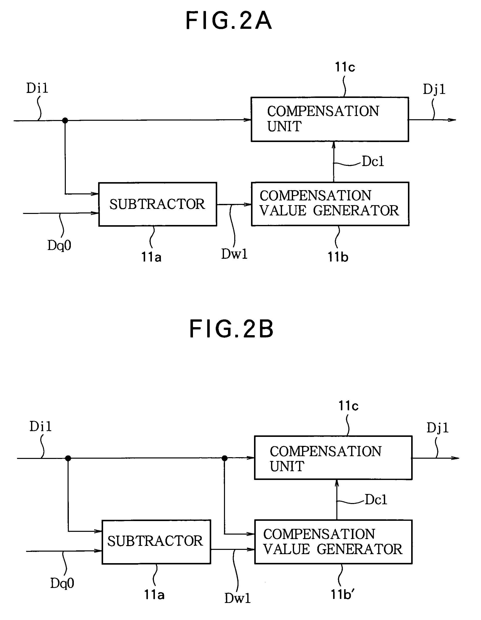
[0117]In the first embodiment, the compensated image data generator 11 calculates a second amount of change between the primary reconstructed preceding frame image data Db0 or the secondary reconstructed preceding frame image data Dp0 and the original current frame image data Di1, and then compensates the voltage-level of the brightness signal or other signal corresponding to the image data of the current frame in accordance with the response speed characteristic and the amount of change in the image data between the current frame and preceding frame, but calculating these image data for each pixel places an increased computational load on the processing unit, which is a problem. The load may be tolerable if the formulas for calculating the compensation data are simple, but if the formulas are complex, the computational load may be too great to handle. In the second embodiment, shown below, the compensation values and amounts to be applied to the image data of the current frame are ...

third embodiment

[0142]In the second embodiment it was shown that it is possible to reduce the computational load by using a lookup table 11d containing pre-calculated compensation values when compensating the voltage level of a brightness or other signal in the image data of the current frame, but the computational load can be further reduced by having the lookup table store compensated image data obtained by compensating the image data of the current frame with the compensation values. Accordingly, in the third embodiment described below, compensated image data obtained by compensating the image data of the current frame with the compensation values are stored in a lookup table, and the compensated image data of the current frame are output by use of the table.

[0143]Except for storing a table of compensated image data obtained by compensating the current frame image data in advance in the compensated image data generator 11 and using the compensated image data as the output of the compensated imag...


PUM

PropertyMeasurementUnit
transmittanceaaaaaaaaaa
image data processingaaaaaaaaaa

Abstract

Consecutive frames of image data are processed for display by, for example, a liquid crystal display. The image data are compressed, delayed, and decompressed to generate primary reconstructed data representing the preceding frame, and the amount of change from the preceding frame to the current frame is determined. Secondary reconstructed data are generated from the current frame image data according to the amount of change. Compensated image data are generated from the current frame image data and the primary and secondary reconstructed data; in this process, either the primary or the secondary reconstructed data may be selected according to the amount of change, or the primary and secondary reconstructed data may be combined according to the amount of change. The amount of memory needed to delay the image data can thereby be reduced without introducing compression artifacts when the amount of change is small.

Description

BACKGROUND OF THE INVENTION[0001]1. Field of the Invention[0002]The present invention relates, in the driving of a liquid crystal display device, to a processing method and a processing circuit for compensating image data in order to improve the response speed of the liquid crystal; more particularly, the invention relates to a processing method and a processing circuit for compensating the voltage level of a signal for displaying an image in accordance with the response speed characteristic of the liquid crystal display device and the amount of change in the image data.[0003]2. Description of the Related Art[0004]Liquid crystal panels are thin and lightweight, and their molecular orientation can be altered, thus changing their optical transmittance to enable gray-scale display of images, by the application of a driving voltage, so they are extensively used in television receivers, computer monitors, display units for portable information terminals, and so on. However, the liquid cr...

Claims


Application Information

Patent Timeline
Patent Type & Authority Patents(United States)
IPC IPC(8): G09G3/36G02F1/133G09G3/20H04N5/66
CPCG09G3/3611G09G2340/16G09G2320/0252A01K61/70
Inventor SOMEYA, JUN
Owner TRIVALE TECH
Why Eureka
Try Eureka