
Method of replacing an abradable portion on the casing on a turbojet fan

a technology of abradable parts and turbojet fans, which is applied in the field of maintenance of turbojets, can solve the problems of long gaskets, long gaskets, and long gaskets, and achieve the effect of better control of the temperature of the adhesive and the surface for bonding

Active Publication Date: 2007-10-09
SN DETUDE & DE CONSTR DE MOTEURS DAVIATION S N E C M A
View PDF5 Cites 28 Cited by
  • Summary
  • Abstract
  • Description
  • Claims
  • Application Information

AI Technical Summary

Benefits of technology

[0015]It will be understood that by using holding sectors and bladders over the heating belt it is possible to put into place progressively the means for compressing the abradable portion that is for bonding to the casing and for heating the adhesive and the surfaces that are to be bonded together. The surfaces are bonded together at ambient temperature and do not require sealing means to be put into place. The holding sectors fitted with their bladders are put into place separately, one after another. This operation is therefore simple, inexpensive, and easy to implement, even with large turbojets, thereby solving the first problem.
[0017]It will be understood that the outside heating belt delivers heat to the adhesive and to the surface for bonding through the casing, i.e. through the outside wall of the casing towards the inner wall. This heating thus opposes any heat loss in the opposite direction and consequently provides better control over the temperature of the adhesive and the surfaces for bonding together, thereby solving the second problem.

Problems solved by technology

That technology is acceptable with small casings, but it becomes lengthy and difficult with the casings of large turbojets, where such casings nowadays have a diameter of as much as 3 meters.
It becomes very difficult to put the vacuum bag into place and to provide leaktightness at the gasket between the flexible film and the casing, since:the gaskets are very long compared with the volume between the flexible film and the casing;numerous fixing holes in the casing need to be sealed off thoroughly, with these holes serving to enable sound-absorbing panels for the engine to be attached to the casing by means of screws;putting the vacuum bag into place becomes dangerous; andobtaining a vacuum inside said bag requires numerous precautions to be taken, together with special means that are expensive and difficult to implement.
That technology also presents the drawback of pressing the abradable portion against the casing with relatively low pressure only, said compression being differential between atmospheric pressure and the relative vacuum obtained inside the vacuum bag.
Another difficulty presented by that technology is controlling the temperature to which the adhesive is raised, since heat losses are large, both by conduction through the material of the casing and by convection to ambient air, with such heat losses becoming very large with large casings.
A first problem to be solyed is to propose a simple and low cost method of replacing an abradable portion on the casing of a turbojet fan in position under the wing of the airplane, and in which the size of the casing is not a handicap.
A second problem to be solyed is to control the entire cycle of adhesive polymerization.

Method used


Image

  • Method of replacing an abradable portion on the casing on a turbojet fan
  • Method of replacing an abradable portion on the casing on a turbojet fan
  • Method of replacing an abradable portion on the casing on a turbojet fan

Examples


Embodiment Construction

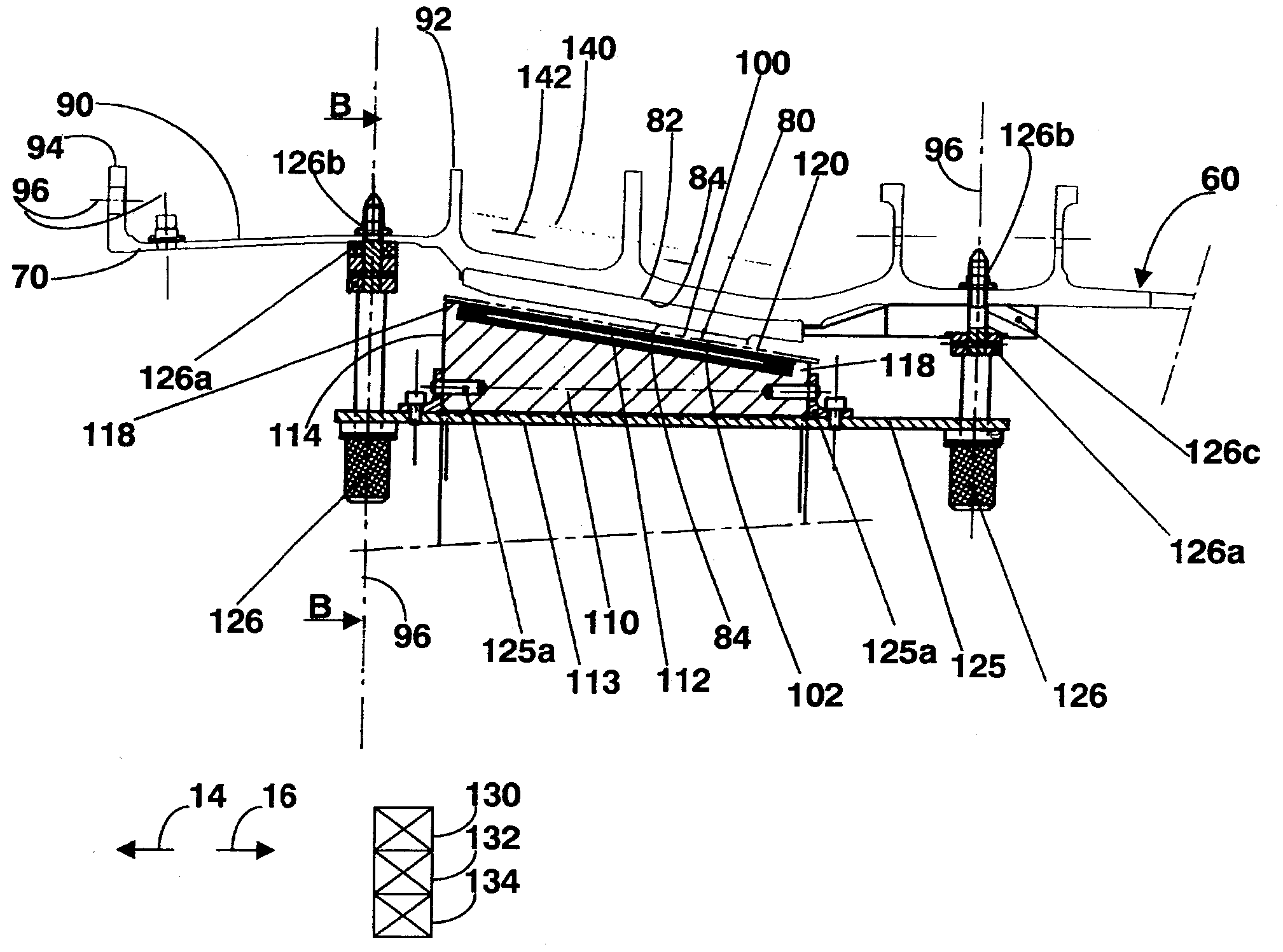
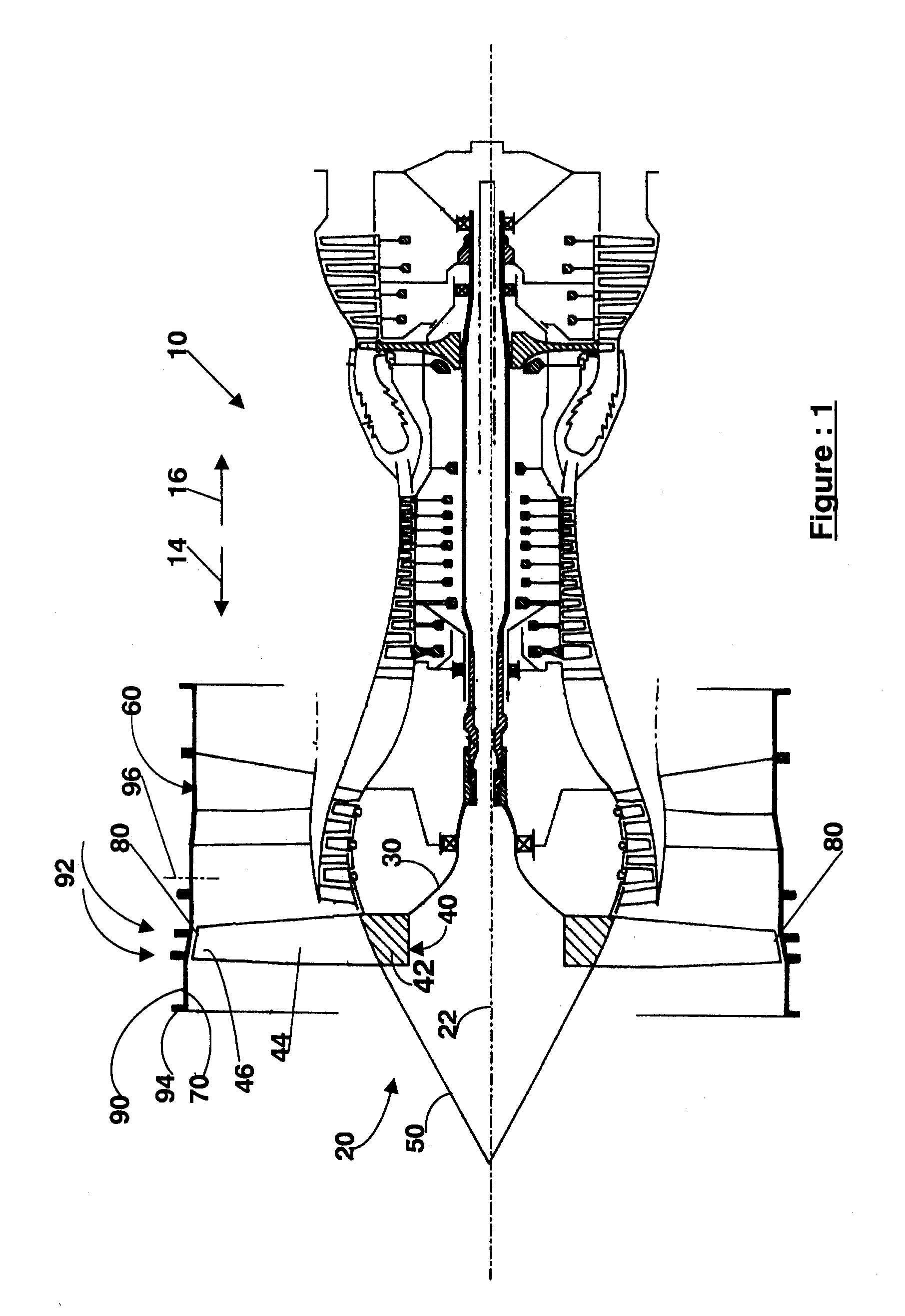
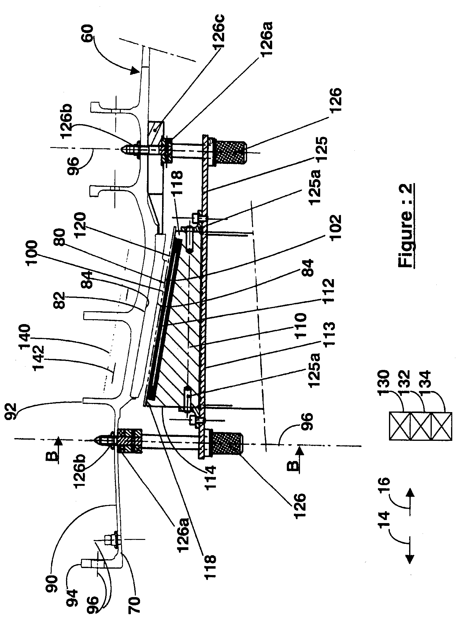
[0023]Reference is made initially simultaneously to FIGS. 1 and 2. For reasons of clarity, the front of the turbojet 10 is referenced 14 and the rear of the turbojet 10 is referenced 16. The turbojet 10 is of the double-flow type and comprises a rotary portion 20 of axis 22 comprising in particular a shaft 30 and a fan stage 40 attached via its hub 42 to the front of the shaft 30, the hub 42 supporting a plurality of blades 44 with the portion of each blade that is furthest from the hub 42 being referred to as its tip 46. The rotary portion 20 also comprises an air inlet cone 50 attached to the front 14 of the hub 42.

[0024]At its front end 14, the turbojet 10 also includes an annular fan casing 60 surrounding the fan stage 40 and open to the front 14. The fan casing 60 is stationary, being centered on the axis 22 and being substantially cylindrical in shape. The fan casing 60 comprises an inside wall 70 against which an annular abradable portion 80 surrounding the blades 44 is bonde...


PUM


Abstract

A simple and low cost method of replacing an abradable portion on the fan casing of a turbojet includes an inside heating belt together with holding sectors therefor are put into place against the abradable portion, each holding sector including an inflatable bladder, and the abradable portion and the inside heating belt being sandwiched in full between the fan casing and the bladders, the holding sectors themselves being held in place by a plurality of straps attached to the fan casing by fixing points.

Description

TECHNICAL FIELD OF THE INVENTION[0001]The invention relates to maintaining turbojets, and more particularly to a method of replacing a damaged abradable portion on the casing of the fan of such a turbojet.STATE OF THE ART AND PROBLEM TO BE SOLVED[0002]An abradable portion on the casing of a turbojet fan is normally replaced by performing the following methods:[0003]1) removing the air inlet cone and the fan stage; 2) mechanically eliminating the damaged abradable portion; 3) preparing surfaces to receive adhesive; 4) bonding a new abradable portion against the casing by the “vacuum bag” technique for bonding composite materials together, which technique consists in covering the abradable portion by a flexible vacuum pouch or “bag” extending between sealing gaskets engaging the casing, the space between the abradable strip and the flexible film being filled with a pumping fabric and the entire system being connected to a source of suction, with heat being delivered by hot air or by m...

Claims


Application Information

Patent Timeline
Patent Type & Authority Patents(United States)
IPC IPC(8): B23P6/00B29C63/00F02K99/00B29C63/28B29C63/34B29C63/48F01D11/12F01D25/28
CPCB23P6/002B29C63/28F01D11/122F01D25/285Y10T29/49764B29C63/34B29C63/481B29C2063/485Y02T50/672F05D2230/80Y10T29/49728Y10T29/49732Y10T29/49719Y10T29/4973Y10T29/49318B29C63/0069B23C2226/27B23C2250/04Y02T50/60
Inventor LE SAINT, JACQUESVERRIERES, ALAINPONSEN, FRANCOISHAMEL, YANNIK
Owner SN DETUDE & DE CONSTR DE MOTEURS DAVIATION S N E C M A
Learn More