PWM buffer circuit for adjusting a frequency and a duty cycle of a PWM signal

Active Publication Date: 2007-10-09
DELTA ELECTRONICS INC
View PDF7 Cites 11 Cited by
  • Summary
  • Abstract
  • Description
  • Claims
  • Application Information

AI Technical Summary

Benefits of technology

[0009]According to another aspect of the present invention, a control circuit for speed of a fan motor includes: a PWM signal generation unit, a PWM buffer circuit, and a driving circuit. The PWM signal generation unit generates a first PWM signal having a first duty cycle. The PWM buffer circuit is coupled to the PWM signal generation unit for converting the first PWM signal into a second PWM signal having a fixed frequency and a second duty cycle. The driving circuit is coupled to the PWM buffer circuit for outputting a driving

Problems solved by technology

The first one of the disadvantages is that the PWM signal S1 to be utilized must have a relatively high frequency, such as 10 kHz or more.
When the PWM signal S1 has a frequency lower than 10 kHz, the operation of the fan motor 12 is adversely influenced by switching

Method used


Image

  • PWM buffer circuit for adjusting a frequency and a duty cycle of a PWM signal
  • PWM buffer circuit for adjusting a frequency and a duty cycle of a PWM signal
  • PWM buffer circuit for adjusting a frequency and a duty cycle of a PWM signal

Examples


Example

[0019]The preferred embodiments according to the present invention will be described in detail with reference to the drawings.

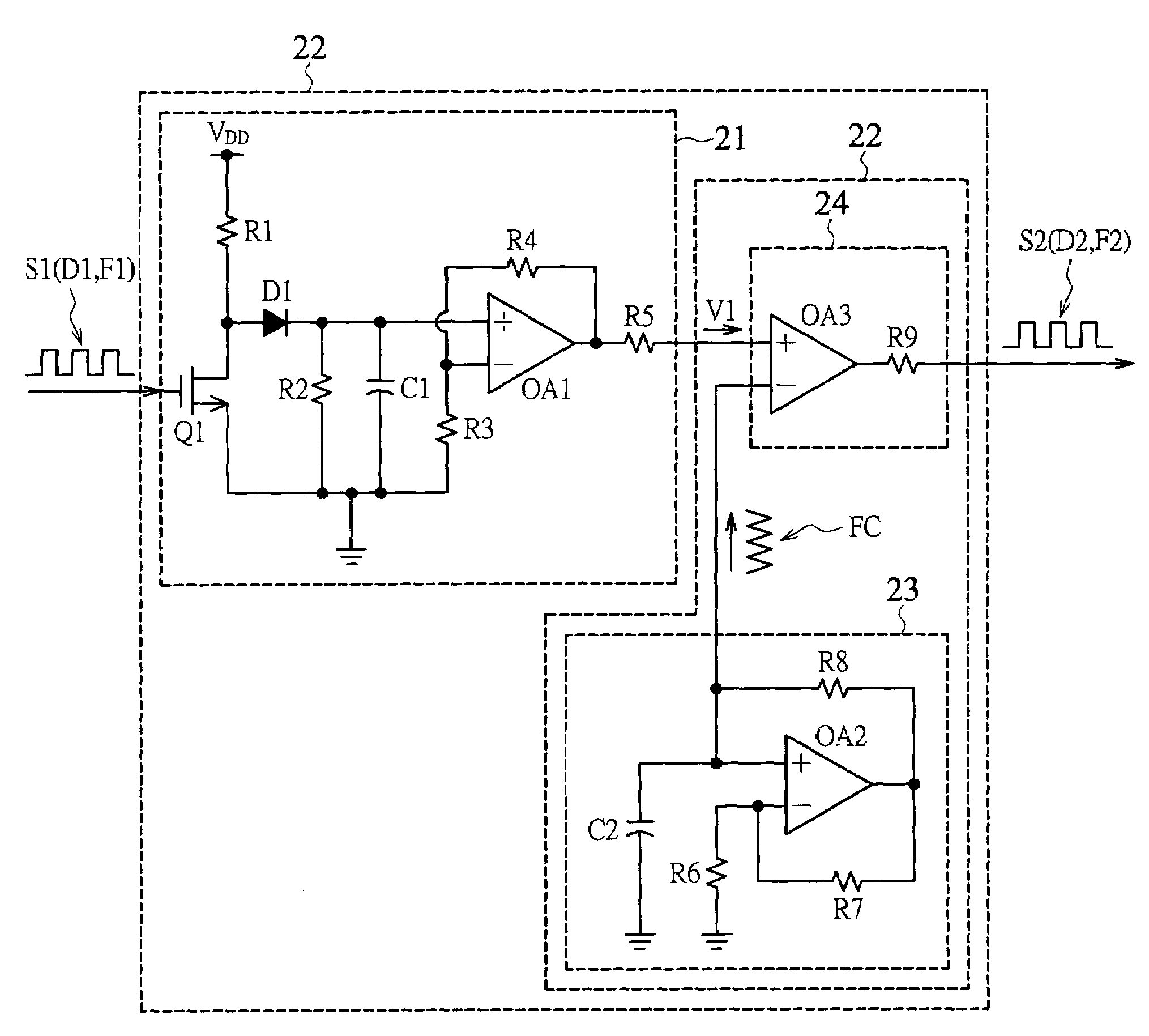
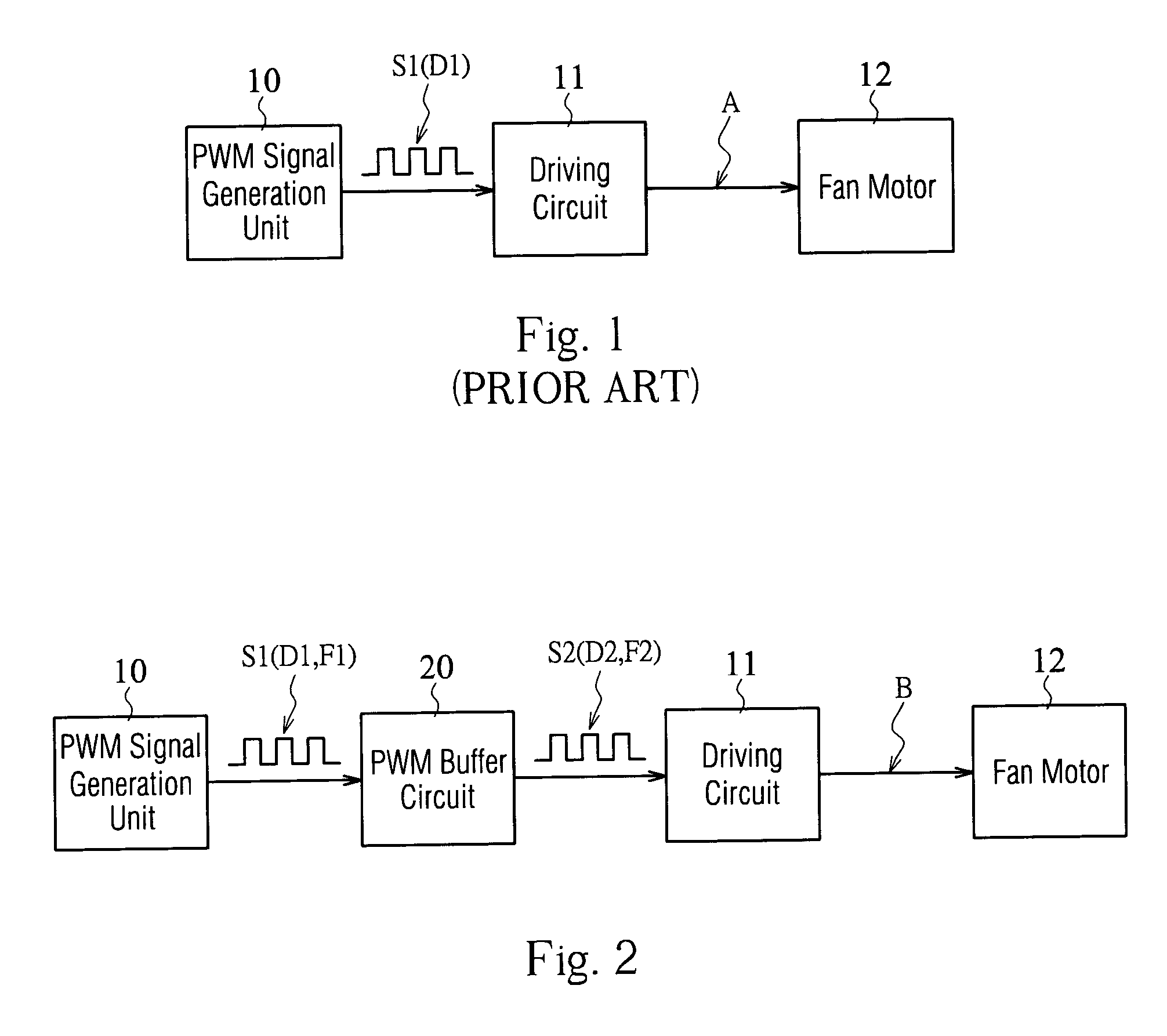
[0020]FIG. 2 is a circuit block diagram showing a control circuit for speed of a fan motor arranged with a PWM buffer circuit 20 according to the present invention. Referring to FIG. 2, the present invention is different from the prior art shown in FIG. 1 in that a PWM buffer circuit 20 is arranged between the PWM signal generation unit 10 and the driving circuit 11 such that a PWM signal S1 output from the PWM signal generation unit 10 is firstly converted into a PWM signal S2, which is subsequently input into the driving circuit 11. Based on the PWM signal S2, the driving circuit 11 outputs a driving signal B to the fan motor 12.

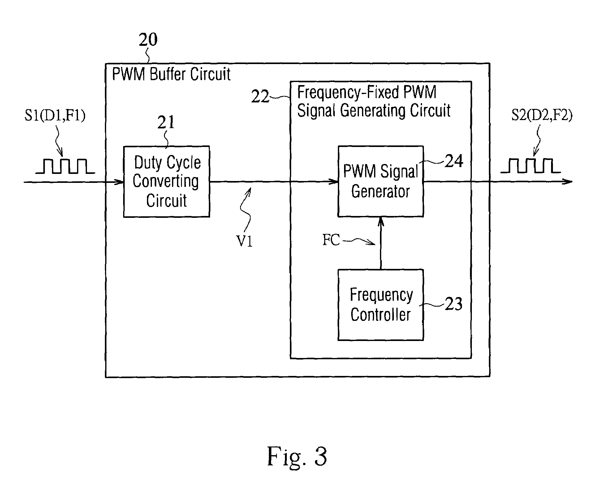
[0021]More specifically, the PWM buffer circuit 20 converts the PWM signal S1 having the duty cycle D1 and the frequency F1 into the PWM signal S2 having a duty cycle D2 and a frequency F2. In the present invention, the duty cycle D...


PUM


Abstract

A PWM buffer circuit includes a duty cycle converting circuit and a frequency-fixed PWM signal generating circuit. The duty cycle converting circuit is used for receiving a first PWM signal and then generating a duty cycle reference voltage on the basis of the first PWM signal. The duty cycle reference voltage is a one-to-one mapping function of the first duty cycle. The frequency-fixed PWM signal generating circuit is used for receiving the duty cycle reference voltage and then outputting a second PWM signal with a fixed frequency. The second PWM signal has a second duty cycle, which is determined in accordance with the duty cycle reference voltage. In addition, the second duty cycle is a one-to-one mapping function of the duty cycle reference voltage.

Description

BACKGROUND OF THE INVENTION[0001]1. Field of the Invention[0002]The present invention relates to a buffer circuit applied with a pulse width modulation (PWM) signal and, more particularly, to a PWM buffer circuit for adjusting a frequency and a duty cycle of a PWM signal.[0003]2. Description of the Related Art[0004]In recent years, a fan for dissipating heat generally operates with a fan motor whose speed is dominantly controlled through utilizing a PWM signal. FIG. 1 is a circuit block diagram showing a control circuit for speed of a fan motor by using a conventional PWM control method. Referring to FIG. 1, a PWM signal generation unit 10 outputs a PWM signal S1 to a driving circuit 11. Based on the PWM signal S1, the driving circuit 11 outputs a driving signal A to a fan motor 12, thereby controlling the speed of the fan motor 12. More specifically, one of signal characteristics of the PWM signal S1 is known as “duty cycle,” i.e., a ratio of a pulse width to a period of the PWM si...

Claims


Application Information

Patent Timeline
IPC IPC(8): H03K3/017H02P7/29H03K5/04H03K7/08
CPCH03K7/08H02P7/29
Inventor CHIU, CHUN-IUNGHUANG, WEN-SHI
Owner DELTA ELECTRONICS INC
Why Eureka
Try Eureka