
Temperature control system with controllable condensation distance for tire tread and sidewall production

A tire tread and temperature control system technology, which is applied in the field of tire processing equipment, can solve the problems that the temperature of the sidewall of the tread does not meet the requirements of the off-line, unfavorable control of the off-line temperature, and large manufacturing consumables, etc., to achieve a wide cooling coverage area , precision, accuracy and convenience, and the effect of controlling the manufacturing process and cost

Pending Publication Date: 2020-12-29
山东玲珑橡胶科技有限公司
View PDF0 Cites 1 Cited by
  • Summary
  • Abstract
  • Description
  • Claims
  • Application Information

AI Technical Summary

Problems solved by technology

As a result, the temperature of the tread and sidewall of the final production does not meet the requirements of the off-line, and water spraying is generally used in the cooling process, and a small part is soaked in water. The manufacturing consumables of the experimental device are large and costly, and water spraying is generally used in the cooling process , the cooling water can only partially or mostly cover the tread, and cannot fully play the role of condensation, resulting in insufficient condensation, which is not conducive to the control of the off-line temperature
Or a small part uses water immersion, the manufacturing consumables of the experimental device are large and the cost is high, especially for the tread and sidewall, and the final production becomes a molded tire. If the temperature control does not meet the requirements, it will cause great safety hazards.

Method used


Image

  • Temperature control system with controllable condensation distance for tire tread and sidewall production
  • Temperature control system with controllable condensation distance for tire tread and sidewall production
  • Temperature control system with controllable condensation distance for tire tread and sidewall production

Examples


Embodiment Construction

[0023] In describing the present invention, it should be understood that the terms "center", "longitudinal", "transverse", "upper", "lower", "front", "rear", "left", "right", " The orientations or positional relationships indicated by "vertical", "horizontal", "top", "bottom", "inner" and "outer" are based on the orientations or positional relationships shown in the drawings, and are only for the convenience of describing the present invention and Simplified descriptions, rather than indicating or implying that the device or element referred to must have a particular orientation, be constructed and operate in a particular orientation, and thus should not be construed as limiting the invention. In addition, the terms "first", "second", etc. are used for descriptive purposes only, and should not be understood as indicating or implying relative importance or implicitly specifying the quantity of the indicated technical features. Thus, a feature defined as "first", "second", etc. ...


PUM


Abstract

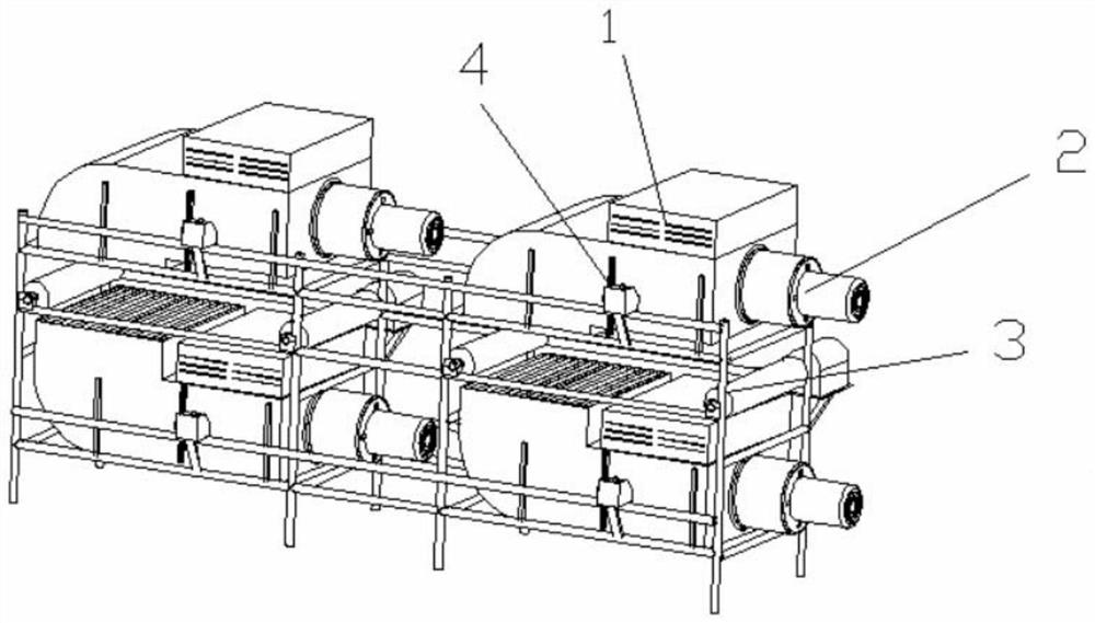
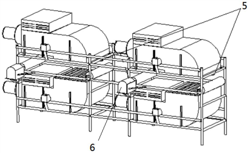
The invention discloses a temperature control system with a controllable condensation distance for tire tread and sidewall production. The temperature control system comprises a support and a conveying mechanism which is arranged on the support and used for transporting tires, wherein a plurality of temperature sensors used for detecting the temperature of the tires are arranged on the support inthe conveying direction of the conveying mechanism, each temperature sensor is at least provided with two sets of cooling assemblies used for cooling the tires, each set of cooling assembly comprisestwo air cooling units which are symmetrical about a tire conveying face, the air spraying ends of every two corresponding air cooling units face the upper side face and the lower side face of the conveying mechanism respectively, each air cooling unit comprises an installation base, and an air blower is arranged on each installation base. Experiments prove that a cooling device is wide in coolingcoverage area, high in cooling efficiency, high in precision, capable of saving cooling liquid and high in energy-saving efficiency, and meanwhile the manufacturing process and cost of a whole experimental device are effectively controlled.

Description

technical field [0001] The invention relates to the technical field of tire processing equipment, in particular to a temperature control system for tire tread sidewall production with controllable condensation distance. Background technique [0002] As far as the current tire temperature control system is concerned, it is unreasonable whether it is intelligent, standardized or structured. In daily production, the offline temperature is often high or low. As a result, the temperature of the tread and sidewall of the final production does not meet the requirements of the off-line, and water spraying is generally used in the cooling process, and a small part is soaked in water. The manufacturing consumables of the experimental device are large and costly, and water spraying is generally used in the cooling process , The cooling water can only partially or mostly cover the tread, and cannot fully play the role of condensation, resulting in insufficient condensation, which is no...

Claims


Application Information

Patent Timeline
Patent Type & Authority Applications(China)
IPC IPC(8): B29C35/16B29C35/00B29L30/00
CPCB29C35/16B29C35/002B29C2035/1658B29L2030/002B29L2030/007
Inventor 王锋战浩陈雪梅
Owner 山东玲珑橡胶科技有限公司
Learn More