
Detection of forwarding problems for external prefixes

a technology of forwarding problems and prefixes, applied in the field of network systems, can solve problems such as difficulty in collocating additional equipment, provider may not be aware of a failure within its network, and the demand for data communication services is growing at an explosive ra

Active Publication Date: 2007-10-09
CISCO TECH INC
View PDF10 Cites 20 Cited by
  • Summary
  • Abstract
  • Description
  • Claims
  • Application Information

AI Technical Summary

Benefits of technology

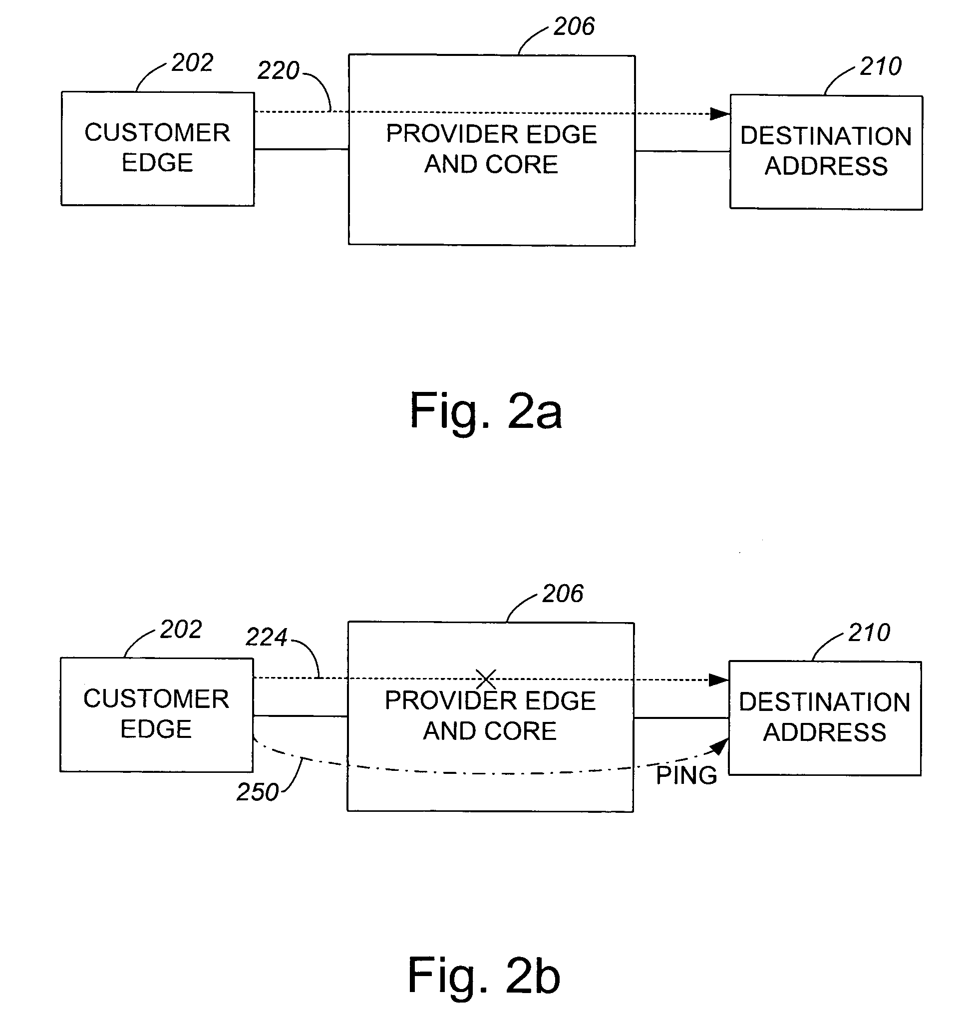
[0016]The ability for a provider to run a tracing procedure within its own network to identify forwarding problems for external prefixes enables the provider to provide improved service to customers. For example, if a provider may run a tracing procedure, e.g., a provider may both effectively initiate pings and also receive the initiated pings within its network, without being prompted by a customer who notices a potential external prefix forwarding problem, the quality of service to customers is enhanced, as the likelihood that customers may experience traffic drops is effectively reduced. By initiating or sending a traceroute message from a source provider edge node which has a destination address specified as a Border Gateway Protocol (BGP) next hop, but effectively terminating the traceroute message at a destination provider edge node, a provider may effectively ping its own network to ascertain whether any forwarding failures occur along a particular path.
[0019]According to another aspect of the present invention, a method for detecting a forwarding problem within an autonomous system includes receiving a message on a destination node from a source node. The message substantially originates at the source node and is intended to be sent through the destination node to a message destination that is an external address which is not an address located within the autonomous system. The message is received on the destination node through a path segment between the source node and the destination node that is a part of an overall path between the source node and the message destination. The method also includes removing the message from the overall path at the destination node to substantially prevents the message from reaching the message destination, and initiating a response from the destination node that is sent along the path segment from the destination node to the source node to indicate that an intermediate node which is along the path segment does not have a forwarding problem.

Problems solved by technology

The demand for data communication services is growing at an explosive rate.
A failure of an intermediate point may be the result of an intermediate point being off line, or of forwarding entries not being properly setup at an intermediate point such that a packet or, in general, traffic passing through that intermediate point is effectively dropped.
Although pings which are sent by customer edges, i.e., customer edge nodes, are useful in enabling node failures within a provider network to be identified, customer edges may not necessarily initiate pings to determine why a forwarded message may not have reached an intended destination address.
As a result, a provider may not be aware of a failure within its network.
A ping generally may not be sent by a node of a provider network to a destination within the provider network to determine if there is a failure within the provider network, as it is often quite difficult to collocate additional equipment at each point in the network to enable such a ping to be sent.
Hence, a provider may not readily determine that an intermediate point within a provider network is not set up to properly forward entries and is potentially dropping traffic.
Therefore, unless a customer initiates a ping and notifies a provider of a potential failure within the provider network, the provider is generally unaware that a failure may exist at one of the nodes within the provider network.
If the provider is unaware of a failure, a failure may not be corrected, and customers which use the provider network may be dissatisfied with the performance of the provider network.

Method used


Image

  • Detection of forwarding problems for external prefixes
  • Detection of forwarding problems for external prefixes
  • Detection of forwarding problems for external prefixes

Examples


Embodiment Construction

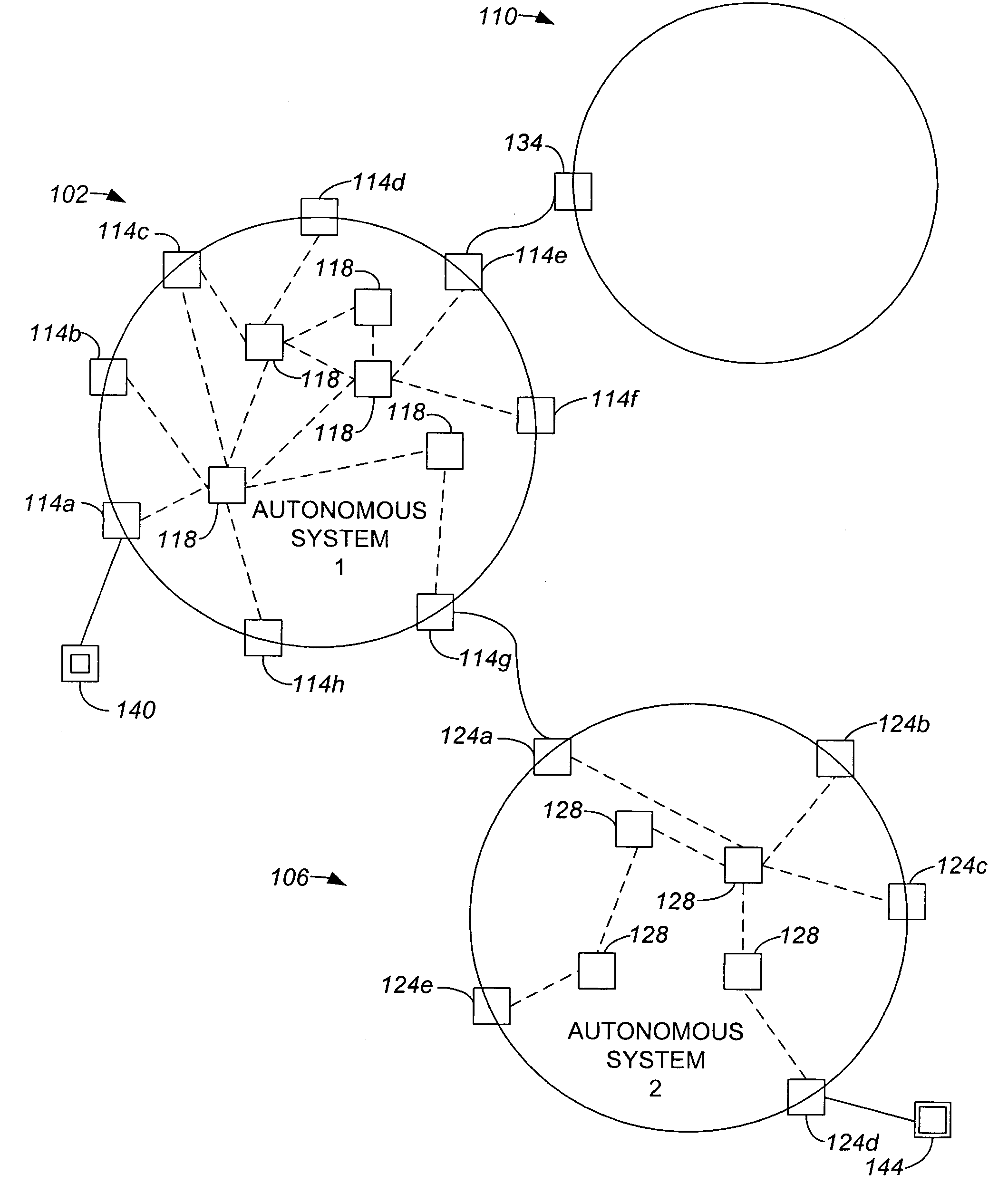
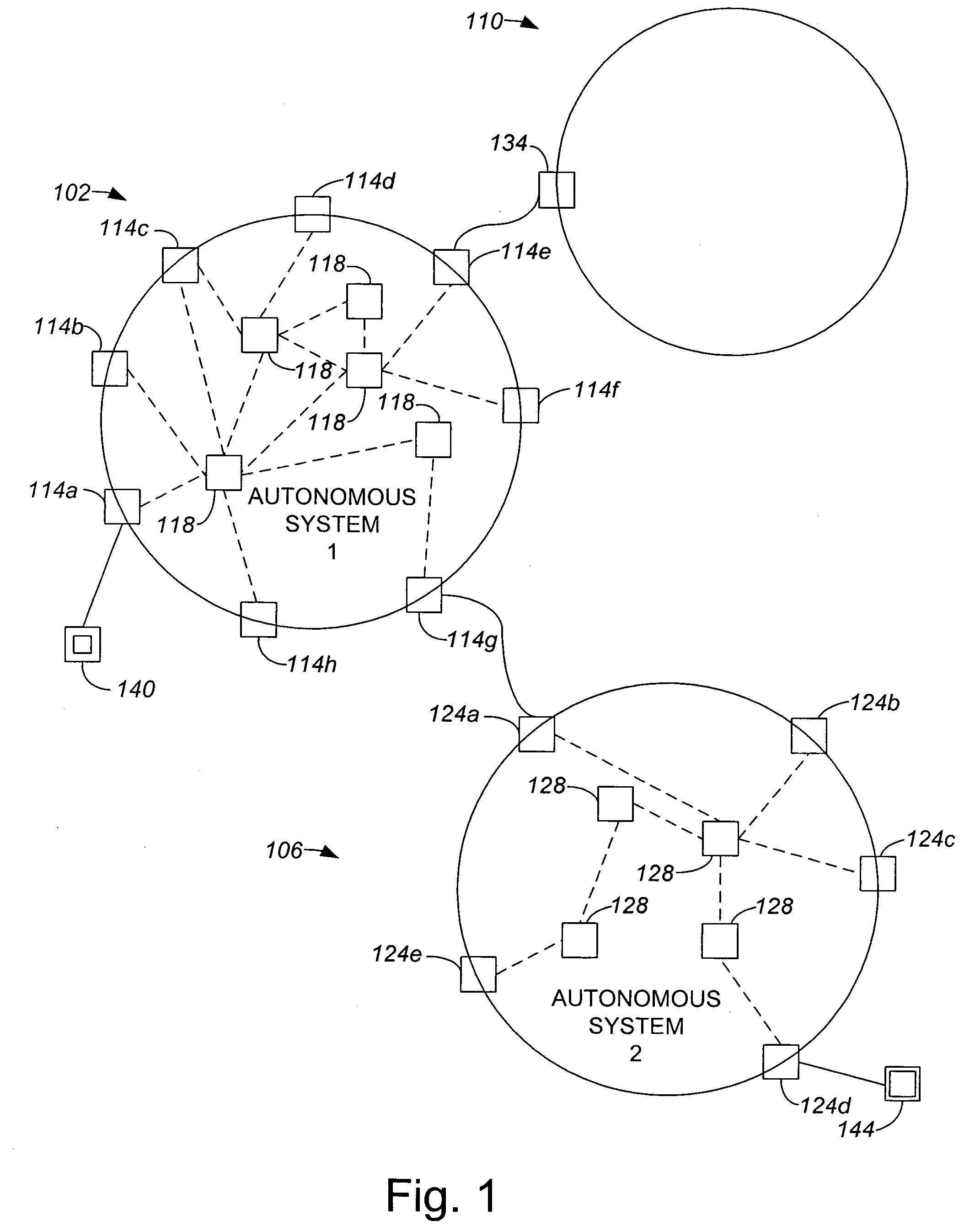
[0034]A network provider is generally unable to determine if there are failures in intermediate points or nodes of its network which prevent messages from being properly forwarded unless a customer who uses the network notifies the network provider of a potential failure within the network. The inability for a network provider to determine on its own that message forwarding may not be properly set up on at least one node of its network is inefficient, since if no customer notifies the network provider of a potential failure, a failed node may remain substantially undetected for a relatively long period of time. When a network provider does not know about a failed node, the network provider may not take steps to rectify the situation. In addition, customers who are unable to successfully send or receive messages through the provider network may be inconvenienced when their messages are lost.

[0035]The ability for a provider to determine whether an autonomous system or network owned by...


PUM


Abstract

Methods and apparatus for enabling a provider to perform a tracing procedure to determine the existence forwarding problems within its network are disclosed. According to one aspect of the present invention, a method for detecting a forwarding problem within an autonomous system includes initiating a message from a source node. The message is sent to a message destination that is an external address relative to the autonomous system. The method also includes forwarding the message from the source node along a path to the external address which includes an intermediate node and a destination node. The message is received on the destination node through a first path segment of the path. Finally, the message is removed from the path at the destination node, and a response that indicates that the intermediate node does not have a forwarding problem is sent along the first path segment to the source node.

Description

BACKGROUND OF THE INVENTION[0001]1. Field of Invention[0002]The present invention relates generally to network systems. More particularly, the present invention relates to enabling a substantially internal trace process to be used to identify nodes within a provider network which are not able to forward external prefixes.[0003]2. Description of the Related Art[0004]The demand for data communication services is growing at an explosive rate. Much of the increased demand is due to the fact that more residential and business computer users are becoming connected to the Internet. Within a network, as for example an optical network, different provider networks, or autonomous systems, may be in communication with one another. For example, an overall network may include multiple autonomous systems which each include various nodes such as routers and servers. For a first customer to communicate with a second customer, the first customer generally initiates the transmission of a packet which ...

Claims


Application Information

Patent Timeline
Patent Type & Authority Patents(United States)
IPC IPC(8): H04L12/26H04L12/56
CPCH04L45/34H04L45/00
Inventor SURI, SHYAM
Owner CISCO TECH INC
Learn More