Elevating device

a technology of lifting device and platform, which is applied in the direction of bridges, building scaffolds, sport apparatus, etc., can solve the problems of high cost of installing such a transport system, heavy and cumbersome traditional devices to move and assemble, and limited use of such devices, so as to achieve the effect of sufficient power, raising and lowering materials and/or people on the platform

Inactive Publication Date: 2007-10-16
KING TOOL & MFG COMPANY
View PDF17 Cites 35 Cited by
  • Summary
  • Abstract
  • Description
  • Claims
  • Application Information

AI Technical Summary

Benefits of technology

[0009]It is a further object of the present invention to provide an elevating device that is light-weight enough that it is portable, but that has sufficient power that it can raise and lower materials and / or people on the platform.

Problems solved by technology

The cost of installing such a transport system can be quite high and is often cost-prohibitive, forcing individuals to move from their homes as their physical abilities change.
First, traditional elevating devices require permanent attachment to a structure such as a tree or a ladder.
Second, the traditional devices tend to be heavy and cumbersome to move and assemble.
Often, use of such devices is limited by how far the elevating device can be transported.
Thus, the height of the devices was limited by the length of the pulley mechanism used.
Finally, some elevating devices are cost-prohibitive, particularly those used in homes and businesses to transport people up steps.

Method used


Image

  • Elevating device
  • Elevating device
  • Elevating device

Examples


Embodiment Construction

OF EMBODIMENTS OF THE INVENTION

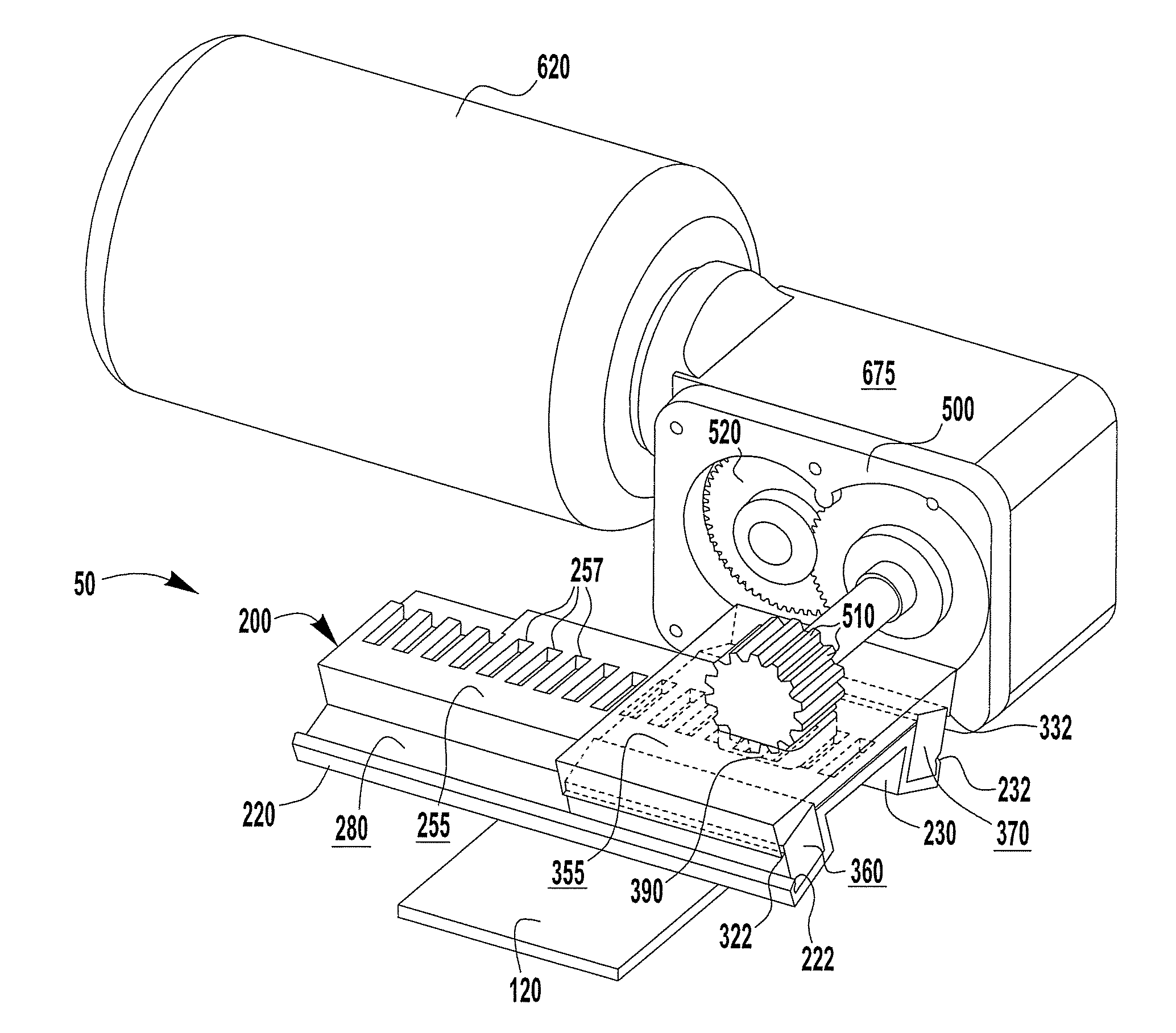
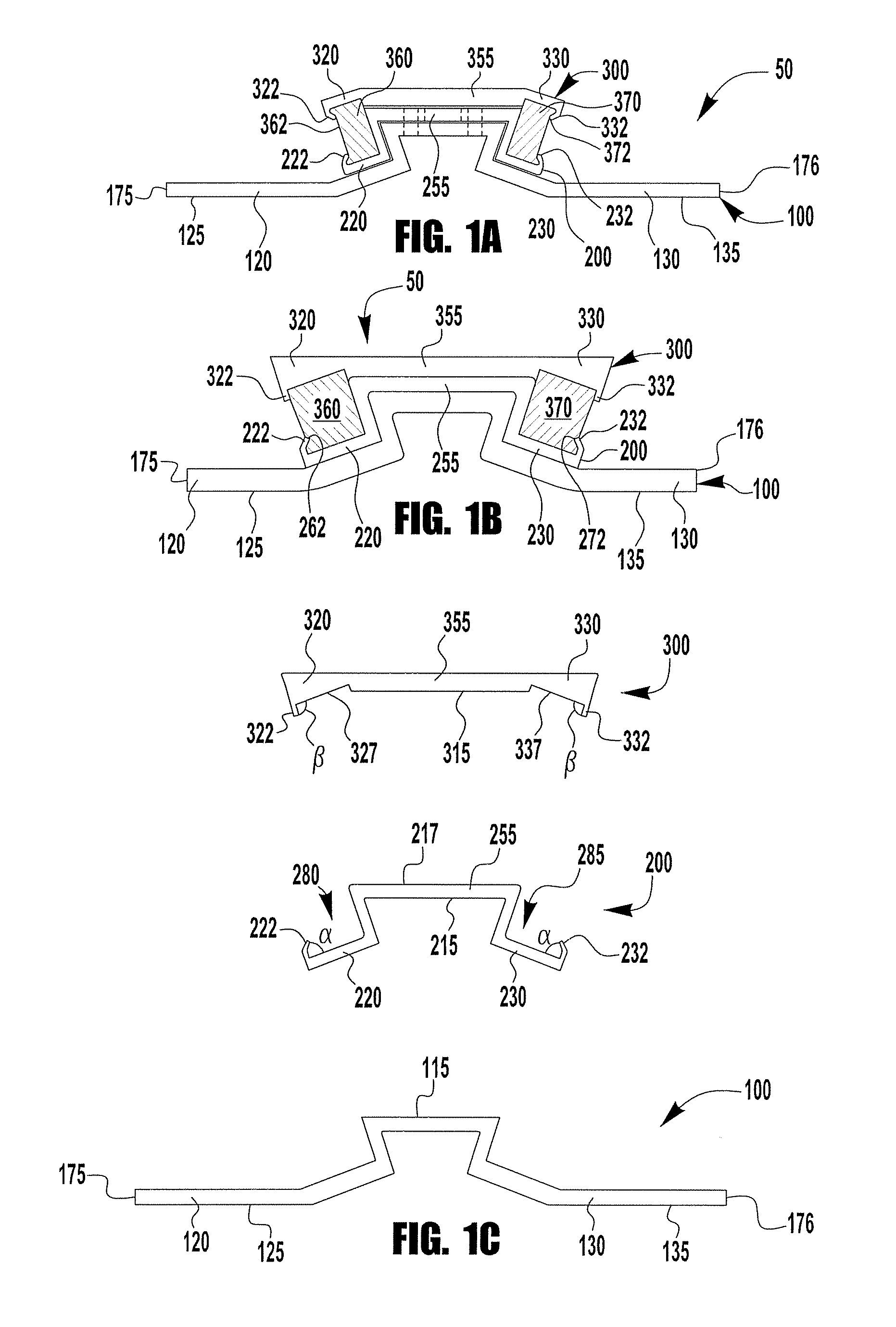
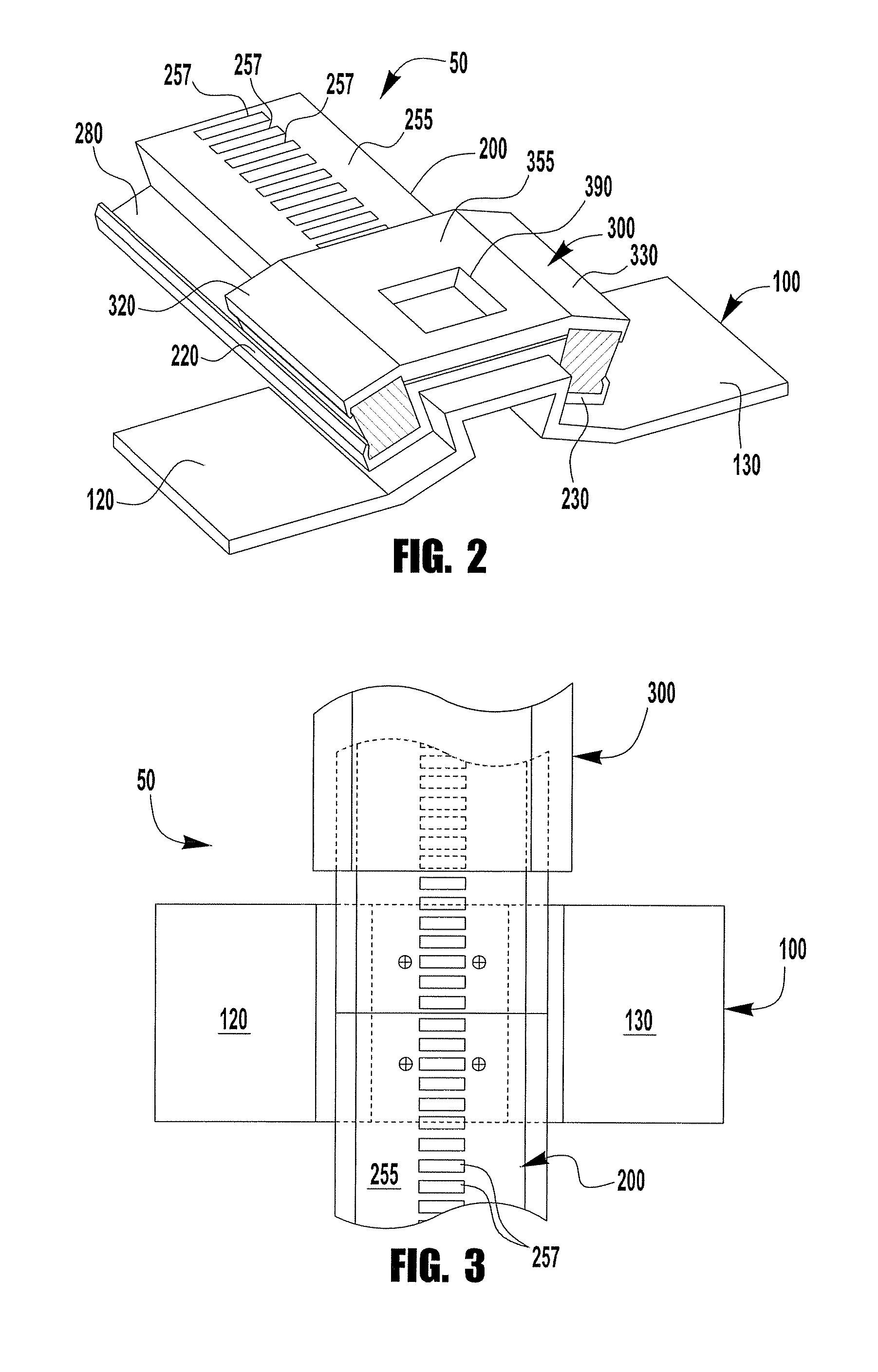
[0023]FIGS. 1A and 1B show cross-sectional views of examples of embodiments of the elevating device 50 of the present invention. In an example, elevating device 50 is portable. In examples, elevating device 50 is able to be either temporarily or permanently mounted to an independent or desired surface of an object or structure. As shown in the figures, and referring particularly to FIGS. 1–4, the elevating device 50 is comprised of at least one securing bracket or first dovetail member 100 that is capable of being mounted on or to the independent surface. In an example, first dovetail member 100 is stationary and is secured to the independent surface using a securing means such as, for example, a bolt, a screw, a strap, a chain, or rope. As discussed in more detail below, independent surfaces may include surfaces of an object or structure such as, for example, trees 700, ladders 800, poles 900, or stairways (not shown). See FIGS. 5–9. First dovetail me...


PUM


Abstract

The elevating device of the present invention is comprised of first, second, and third dovetail members that are interlockingly engaged. First dovetail member is secured to an object or an independent surface such as a tree or a ladder. First and second dovetail members are stationary and third dovetail member is moveable. Slide bars are secured to third dovetail member. Slide bars slidably engage a guide track. There is a gear that engages slots in the second dovetail member elevating third dovetail member as the slide bars slidably engage the guide track. There is a platform for holding people or objects that is secured to third dovetail member. As the gear rotates and elevates third dovetail member, the platform secured thereto is also elevated.

Description

CLAIM OF PRIORITY[0001]This application claims priority to U.S. Provisional Application No. 60 / 660,527 filed on Mar. 10, 2005.FIELD OF THE INVENTION[0002]The present invention relates generally to an elevating device, and more specifically to a device for elevating materials and people from the ground to a higher surface.BACKGROUND OF THE INVENTION[0003]Elevating devices are known in the prior art, and many industries rely on elevating devices to move materials or people off the ground to a higher location. For example, hunters often sit on platforms in trees so that they have a clear view of the territory in which they are hunting. Traditionally, these platforms have been permanent structures that are built around the tree trunk and that require a ladder to access. Likewise, contractors and painters often use an elevating device with a platform to move building and painting tools and supplies from one level to a higher level in order to work on buildings or other structures that ar...

Claims


Application Information

Patent Timeline
Patent Type & Authority Patents(United States)
IPC IPC(8): E04G3/00B66B9/00
CPCA01M31/02E06C7/12E04G3/28B66B9/16
Inventor KIRALY, JOHN J.
Owner KING TOOL & MFG COMPANY
Why Eureka
Try Eureka