Process for de-inking paper pulp and flotation cell used for this process
Inactive Publication Date: 2007-10-16
LAMORT KADANT
View PDF3 Cites 0 Cited by
Summary
Abstract
Description
Claims
Application Information
AI Technical Summary
This helps you quickly interpret patents by identifying the three key elements:
Problems solved by technology
Method used
Benefits of technology
Benefits of technology
[0015]Thus, the purpose of the invention is to provide a process and a flotation cell allowing to reduce the energy consumption, to limit the rejections, but also allowing a higher modularity than what is the case for the current cells.
[0018]There is created an acceleration of the speed of the pulp at the location of said bubble passageways, in order to thus aspire the bubbles leaving said passageways, to mix them with the pulp, said acceleration of the pulp being achieved by gradually reducing the cross-section of the pulp passageway on said guiding means immediately upstream of said bubbles passageways.
[0027]the raising of the bubbles is prevented immediately behind said bubble passageways, in order to oblige the bubbles to pass directly through said passageways;
[0037]narrowing organs extending inside the guiding path, so as to gradually reduce the cross-section for the passing through of the pulp immediately upstream of said bubble passageways of each stage of the cell, in order to create an acceleration of the speed of the pulp at the location of said bubble passageways, to thus aspire the bubbles leaving said passageways, in order to mix them with the pulp.
[0043]the cell includes narrowing organs extending inside the guiding path, so as to gradually reduce the cross-section of passing through of the pulp immediately upstream of said bubble passageways of each stage of the cell;
Problems solved by technology
Even though these flotation cells are generally satisfactory, their energy consumption is relatively high.
Method used
Image
Click on the blue label to locate the original text in one second.
Reading with bidirectional positioning of images and text.
Examples
first embodiment
[0077]the invention is shown in FIGS. 1 to 12.
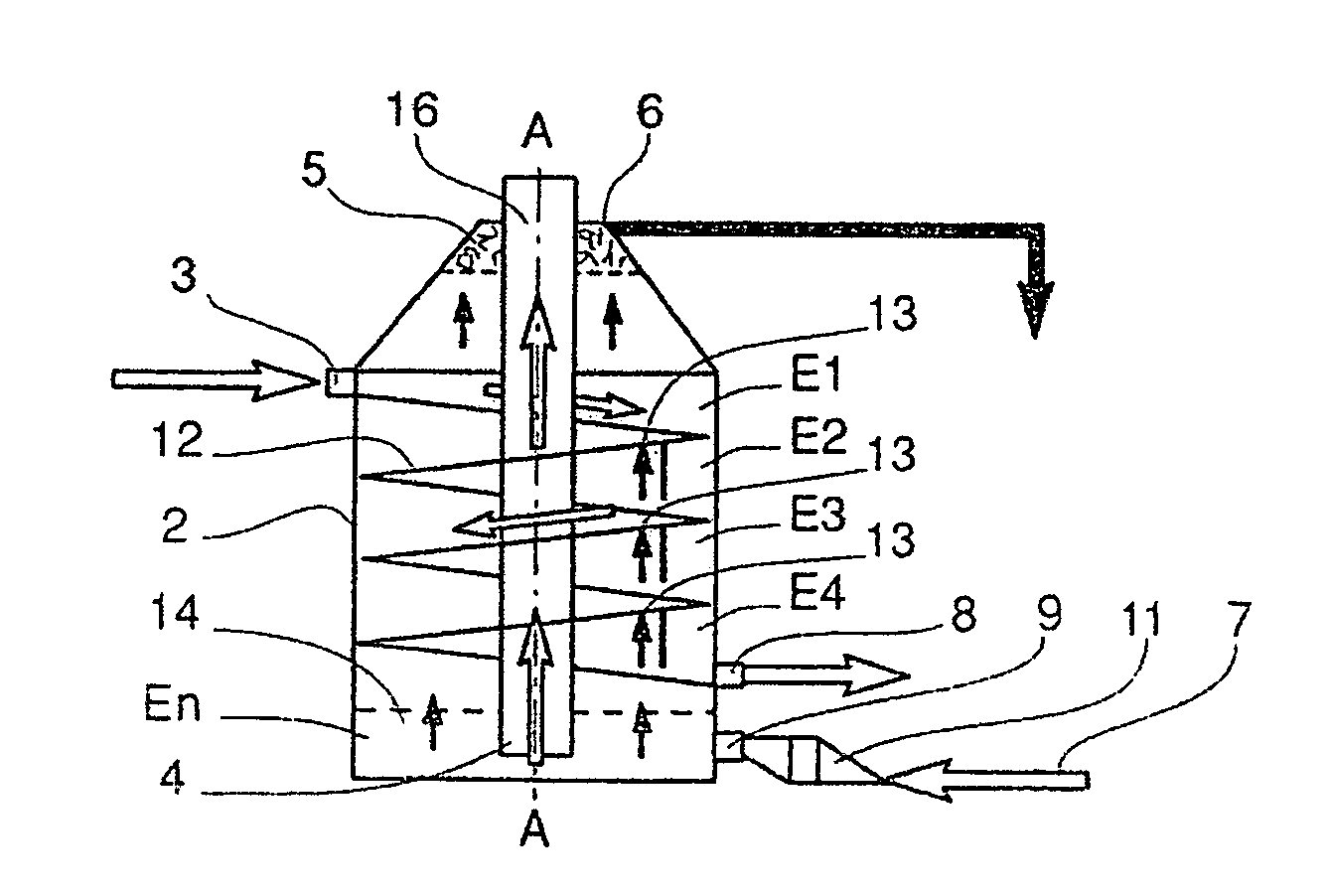
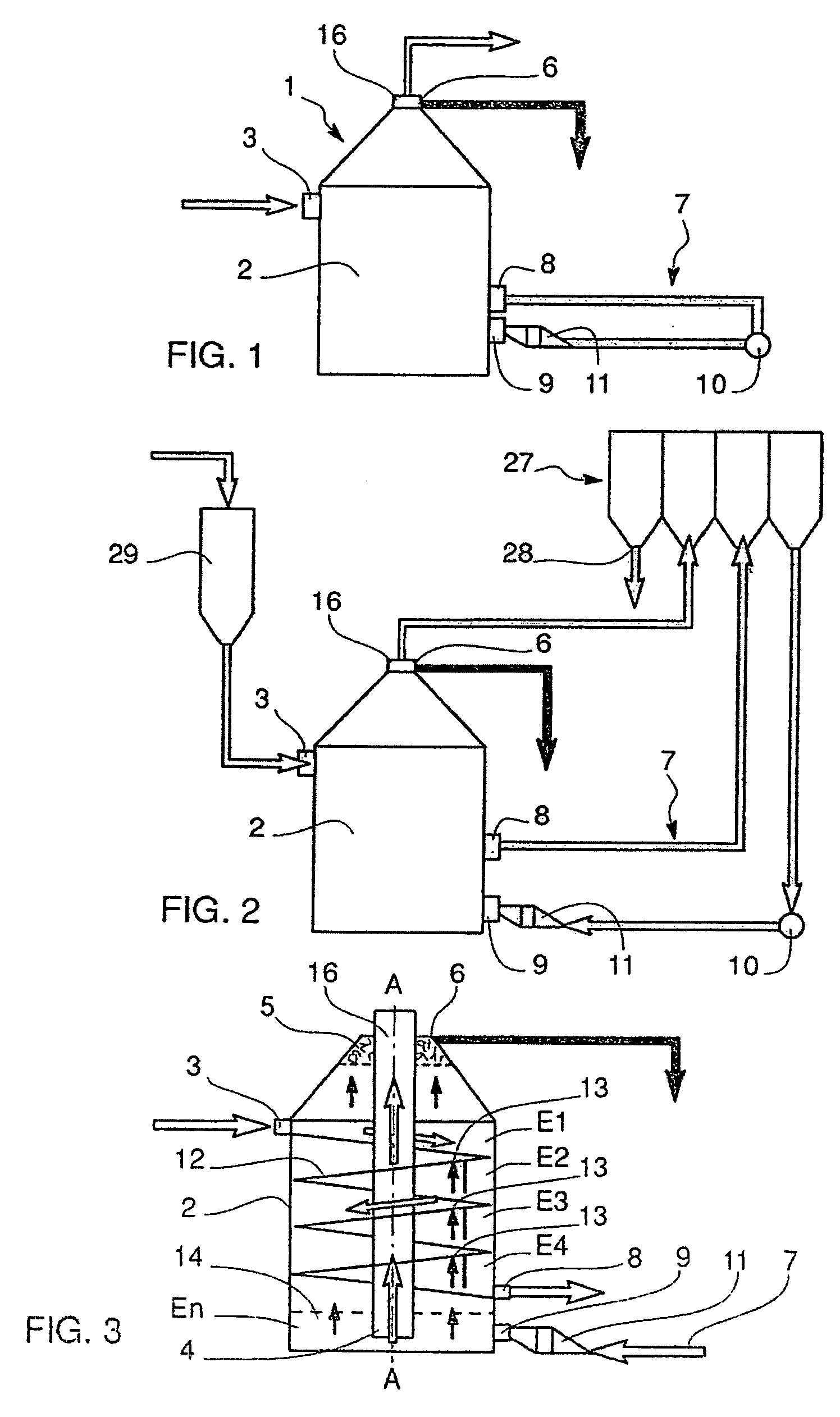
[0078]The flotation cell 1 comprises an enclosure 2 with vertical axis A-A. In this first embodiment, this enclosure is cylindrical. It includes, in its upper portion, a main inlet 3 for the paper pulp to be de-inked and, in its lower portion, a main outlet 4 for the de-inked pulp.
[0079]The pulp to be de-inked is supplied under a certain pressure into the main inlet 3 and moves from the top to the bottom, passing through successive stages E1, . . . En, to be finally evacuated through the main outlet 4.
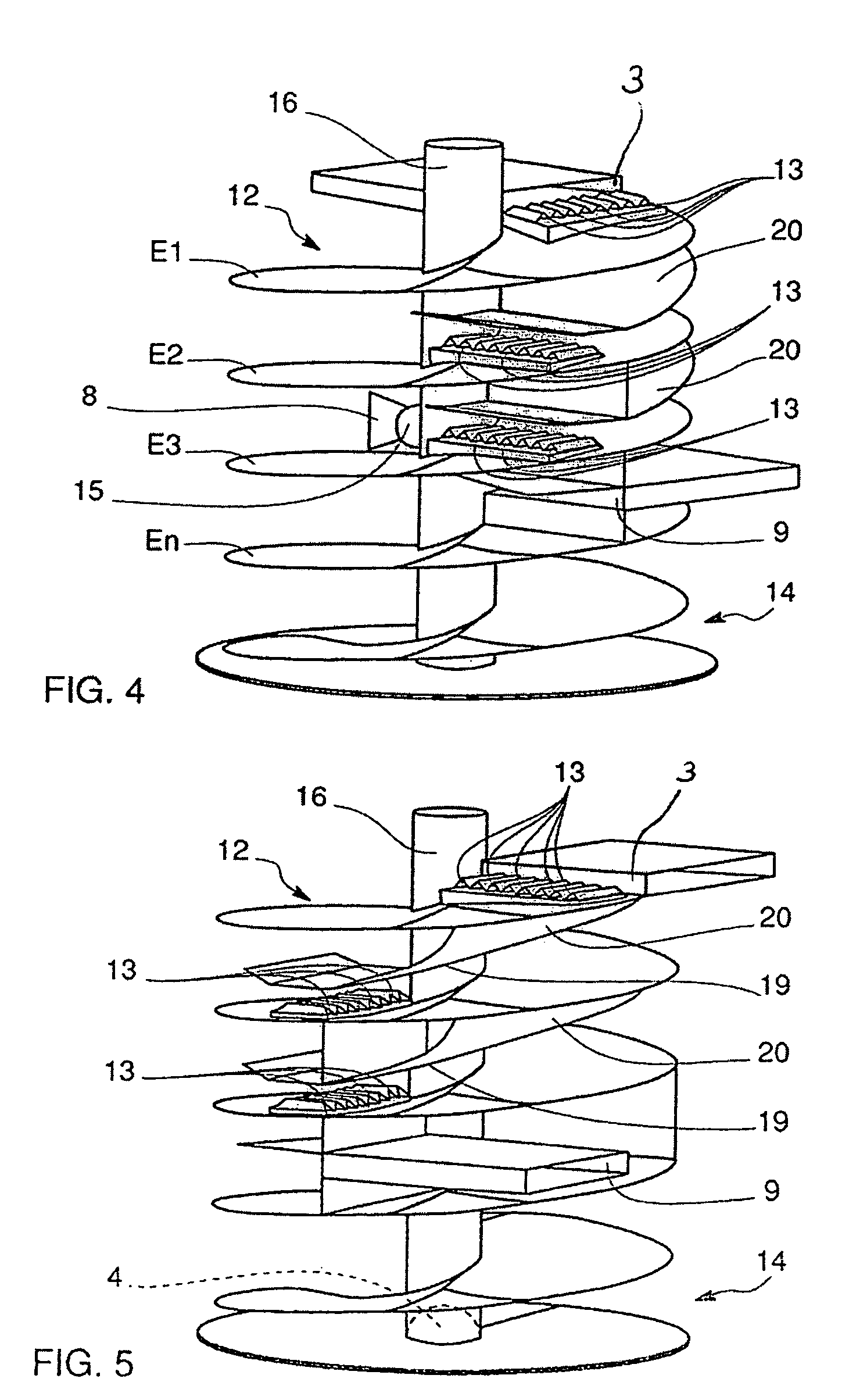
[0080]During its moving downwards, the pulp passes through these successive stages E1, . . . En, which, in their upper portion, are provided with bubble passageways 13, the bubbles being introduced into the lower portion of the enclosure 2. The number ‘n’ is generally about 10 and thus corresponds to 10 stages.
[0081]The bubbles pass through these passageways 13 from one stage to a higher stage, while being mixed again with the pulp in each ...
second embodiment
[0118]FIGS. 13 and 14 schematically show the flotation cell 30 according to the invention. Identical or similar elements are designated by the same reference numerals as the elements already described with reference to FIGS. 1 to 12.
[0119]The flotation cell 30 includes an enclosure 31 with a globally parallelepipedal shape, here rectangular and much longer than wide, inside which are arranged means for guiding the pulp from the top to the bottom, from an upper stage to a lower stage. These guiding means include elongated transverse elements 32 extending on both sides of the axis A-A of the enclosure, in order to form a zigzag guiding path.
[0120]Each transverse element 32 connects two opposite side walls 33 parallel to each other. In the example shown, each transverse element 32 has an upper surface which is primarily horizontal, whereas its lower face is inclined upwardly, in order to guide the bubbles released from the pulp during their upward movement.
[0121]The end (32′) of the tr...
PUM
Property
Measurement
Unit
Flow rate
aaaaa
aaaaa
Speed
aaaaa
aaaaa
Shape
aaaaa
aaaaa
Abstract
The cell includes an enclosure having, at the top, a main inlet for the pulp to be de-inked and, at the bottom, a main outlet for the de-inked pulp. The pulp from the top to the bottom, passes through successive stages provided with bubble passageways introduced into the lower portion of the enclosure, and the bubbles rise to the top, to form a foam. The cell includes pulp a guiding mechanism forming a guiding path and in which the bubble passageways are provided for. The guiding mechanisms are, on their lower face, inclined upwards in order to guide the bubbles towards the bubble passageways.
Description
RELATED U.S. APPLICATIONS[0001]Not applicable.STATEMENT REGARDING FEDERALLY SPONSORED RESEARCH OR DEVELOPMENT[0002]Not applicable.REFERENCE TO MICROFICHE APPENDIX[0003]Not applicable.FIELD OF THE INVENTION[0004]The present invention relates to a process for de-inking paper pulp and a flotation cell used for this process.[0005]The present invention more particularly relates to the de-inking of paper pulp proceeding from old papers one wants to re-use.BACKGROUND OF THE INVENTION[0006]Old papers are first of all converted into the state of pulp by an apparatus commonly referred to as pulper and this pulp is then depleted from its various foreign bodies, referred to as contaminants, by causing it to pass through sieves. However, after this elimination of the contaminants, the pulp contains ink particles which should be eliminated in order to obtain a quality paper.[0007]The pulp depleted from the coarse foreign bodies comprises three types of components, namely the fibers, the fines whi...
Claims
Application Information
Patent Timeline
Application Date:The date an application was filed.
Publication Date:The date a patent or application was officially published.
First Publication Date:The earliest publication date of a patent with the same application number.
Issue Date:Publication date of the patent grant document.
PCT Entry Date:The Entry date of PCT National Phase.
Estimated Expiry Date:The statutory expiry date of a patent right according to the Patent Law, and it is the longest term of protection that the patent right can achieve without the termination of the patent right due to other reasons(Term extension factor has been taken into account ).
Invalid Date:Actual expiry date is based on effective date or publication date of legal transaction data of invalid patent.

