Impact resistant lens, frame and tools and method for making same

a technology of lens and frame, applied in the field of lenses, can solve the problems frame failure generally considered, and protective oriented eyewear/goggles edging/beveling methods suffering certain common drawbacks, so as to reduce the resistance of a frame to breakage or failure, eliminate negative image effects, and reduce the effect of lens to frame design weakness

Inactive Publication Date: 2007-10-16
DAGOSTINO SAVINO
View PDF6 Cites 9 Cited by
  • Summary
  • Abstract
  • Description
  • Claims
  • Application Information

AI Technical Summary

Benefits of technology

[0025]In order to address the shortcomings of the aforementioned prior art, according to at least one aspect the present invention provides a corrective lens comprising a lip having substantially no corrective power that can be employed in conjunction with ophthalmic frames or goggles in which the frames / goggles eyewire has matching contours of the lens edge. The arrangement according to at least one aspect of the present invention increases the resistance of a frame to breakage or failure of retaining the lenses in the frame when impacted by an object. In accordance with at least one aspect of the present invention, a corrective / ophthalmic lens comprises a lip extending from an outer anterior lens edge and a radial groove adjacent and parallel to the lens lip posterior surface. The lens lip size is variable, determined by frame function and design, i.e., the degree of impact protection that is necessary. The lip preferably has little or no corrective power, eliminating negative image effects associated with corrective lens edges and current methods of lens edge bevels.
[0026]The posterior surface of the lens impact lip is beveled with a curvature that preferably substantially matches and coincides with the lens anterior curves, producing a lip with no corrective, low residual power effect or negative image effects. Due to the absence of image change and effects through the lens impact lip, in one aspect the present invention eliminates restrictions to the size of the impact lip. Accordingly, the lens impact lip can now be made larger providing a greater surface area of frame eyewire to be utilized upon impact of an object.
[0027]Beveling according to the present invention permits the lens impact bevel to be shifted anteriorly or posteriorly according to lens corrective strength and / or function for maximizing lens protective and cosmetic values without jeopardizing the integrity of the frame with respect to impact protection. The shifting of beveled placement directly and proportionally affects the lens impact with thickness. For example, a posterior shift of the lens bevel accommodates and disguises lens thickness and increases the impact lip thickness producing a greater protective and cosmetic value.

Problems solved by technology

Frame failure is generally considered to consist of any detachment of the lens from the frame or any full thickness penetration of the lens.
However, these methods of edging / beveling lenses for sport and protective oriented eyewear / goggles suffer certain common drawbacks.
In addition, as with all channel eyewire retention systems (V-channel or flat lip), there is an inherent weakness in the lens to frame design due to a division of strength and function within the frame eyewire.
Unfortunately, methods for enhancing lens cosmetic value do not apply for protective eyewear.
With an increased lens size, the lens becomes thicker and a rise in negative image effects including peripheral lens distortion occurs.
When combined with a larger lens size the thickness results are alarming.
With the increased lens edge thickness, residual thickness becomes a greater issue in that, even with posterior shifting capabilities (where possible) a lens must not protrude from the posterior surface of the frame.
The steeper curve also increases the lens edge and bevel angles, amplifying the unwanted negative image and cosmetic effects to both wearer and onlookers.
Although impact protective, these designs exaggerate the same negative aspects that the optical industry has been trying to minimize.
The hide-a-bevel method, due to its minimal bevel, and current retention lip designs are inadequate to accommodate large wrap-type eyewear for the reasons mentioned hereinabove.
The frame designs accommodate a lens v-beveled edge, which creates a wedge effect that can result in eyewear splitting along the channel apex.
The hide-a-bevel is not effective in addressing the problems associated with wrap-type eyewear because of insufficient bevel surface.
The use of heat for lens insertion for plastic frames can give rise to significant drawbacks.
For example, human errors are possible because there are no instruments to accurately measure the amount of heat needed for different types of plastic in frames of varying thicknesses, compounded by varying edge thickness of a lens due to corrective power and shape.
Heat insertion can cause a warping and / or twisting of the frame eyewire, changing the contact points of lens to frame.
Stretching causes weak points along the eyewire and throws off the sizing ratio of frame to lens.

Method used


Image

  • Impact resistant lens, frame and tools and method for making same
  • Impact resistant lens, frame and tools and method for making same
  • Impact resistant lens, frame and tools and method for making same

Examples


Embodiment Construction

[0044]In the following description, for purposes of explanation, specific numbers, materials and configurations are set forth in order to provide a thorough understanding of the invention. It will be apparent, however, to one having ordinary skill in the art, that the invention may be practiced without these specific details. In some instances, well-known features may be omitted or simplified so as not to obscure the present invention. Furthermore, reference in the specification to “one embodiment” or “an embodiment” means that a particular feature, structure or characteristic described in connection with the embodiment is included in at least one embodiment of the invention. The appearances of the phrase “in one embodiment” in various places in the specification are not necessarily all referring to the same embodiment.

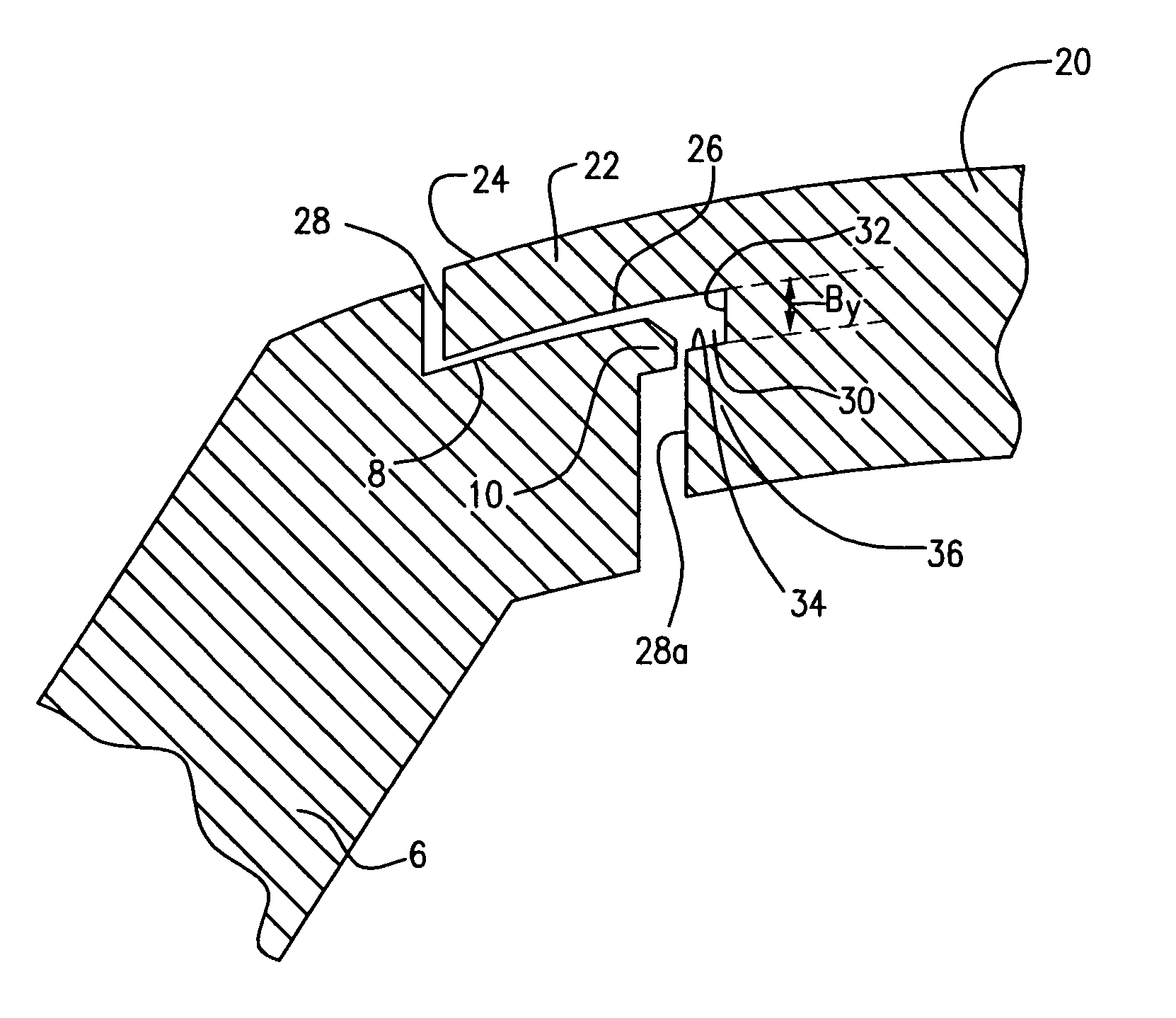
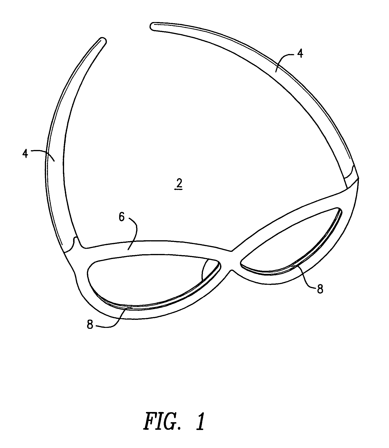
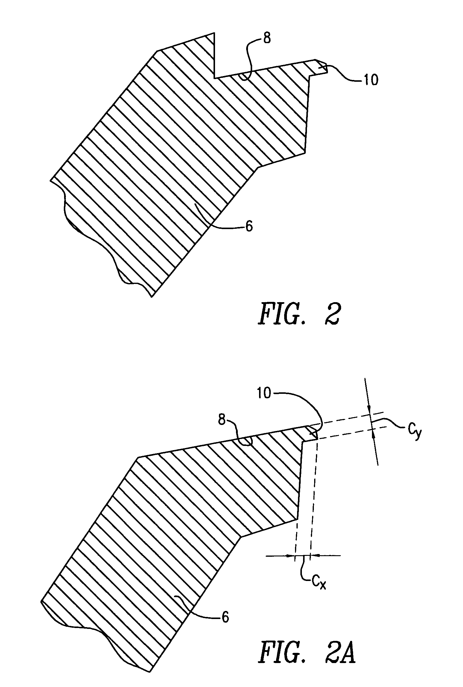
[0045]Now referring to FIG. 1 eyewear 2 in accordance with at least one aspect of the present invention is disclosed comprising temples 4, lens retention body 6 and e...


PUM


Abstract

A corrective / ophthalmic lens comprising an impact lip extending from an anterior lens edge and a radial groove adjacent and parallel to the lens lip posterior surface, an eyewear system containing a corrective / ophthalmic lens and a method of making a lens is provided. The lens impact lip size is variable, determined by frame function and the degree of impact protection that is necessary. A posterior surface of the lens impact lip is beveled with a curvature that preferably substantially matches and coincides with the lens anterior curves, producing a lip with no corrective, low residual power effect or negative image effects. Due to the absence of image change and effects through the lens impact lip, in one aspect the present invention eliminates restrictions to the size of the impact lip.

Description

CROSS REFERENCE TO RELATED APPLICATION[0001]This application claims the benefit of U.S. Provisional Patent Application No. 60 / 553,455, entitled Cosmetic Impact Bevel For Eyewear by inventor Savino D'Agostino, filed Mar. 16, 2004, the entire disclosure of which is hereby incorporated by reference.BACKGROUND OF THE INVENTION[0002]This application is directed to lenses and more particularly to beveled eyewear lenses, methods for producing such lenses, eyewear incorporating such lenses and a tool for making such lenses.[0003]Protective eyewear for sports activities is widely recommended by safety and sport organizations for individuals participating in any sport activity. Many different designs of protective prescription sport eyewear exist, with varying degrees of protection depending on the range of danger associated with the particular sport. Selection charts are published which illustrate the different types of protection available and set forth recommendations as to which of the pr...

Claims


Application Information

Patent Timeline
Patent Type & Authority Patents(United States)
IPC IPC(8): G02C1/00G02C7/02B24B9/14B24D5/02G02C1/06
CPCB24B9/14B24D5/02G02C7/02G02C1/06G02C1/10G02C1/00
Inventor D'AGOSTINO, SAVINO
Owner DAGOSTINO SAVINO
Why Eureka
Try Eureka