System and method for efficient, high-resolution microwave imaging using complementary transmit and receive beam patterns

a beam pattern and beam technology, applied in the field of microwave imaging, can solve the problems of scaling up, the number of antenna elements, and therefore the cost of the array, and the obstacle of quadratic cost dependency

Active Publication Date: 2007-10-16
AGILENT TECH INC
View PDF38 Cites 32 Cited by
  • Summary
  • Abstract
  • Description
  • Claims
  • Application Information

AI Technical Summary

Problems solved by technology

However, the number of antenna elements, and therefore the cost of the array, is proportional to (L / λ)2.
This quadratic cost dependency is an obstacle to either scaling up the size of an array to increase the addressable field of view or reducing the wavelength to increase the resolution.
However, sparse arrays produce multi-lobed antenna patterns.
Thus, as the sparseness of the array is increased, the signal loss increases as the fourth power.
In addition, the background noise (often referred to as “clutter”) that results from stray radiation further decreases the SNR for sparse arrays for several reasons.
Second, the remaining (occupancy) area geometry generally produces sidelobes that change direction in a poorly controlled fashion as the antenna phasing changes.
Thus, sparse arrays result in an increase in signal loss and a decrease in SNR.
Therefore, what is needed is a cost-effective antenna array design for use in microwave imaging that results in a high AFOV without high power-law increases in signal loss or decreases in SNR.

Method used


Image

  • System and method for efficient, high-resolution microwave imaging using complementary transmit and receive beam patterns
  • System and method for efficient, high-resolution microwave imaging using complementary transmit and receive beam patterns
  • System and method for efficient, high-resolution microwave imaging using complementary transmit and receive beam patterns

Examples


Embodiment Construction

[0029]As used herein, the terms microwave radiation and microwave illumination each refer to the band of electromagnetic radiation having wavelengths between 0.3 mm and 30 cm, corresponding to frequencies of about 1 GHz to about 1,000 GHz. Thus, the terms microwave radiation and microwave illumination each include traditional microwave radiation, as well as what is commonly known as millimeter-wave radiation.

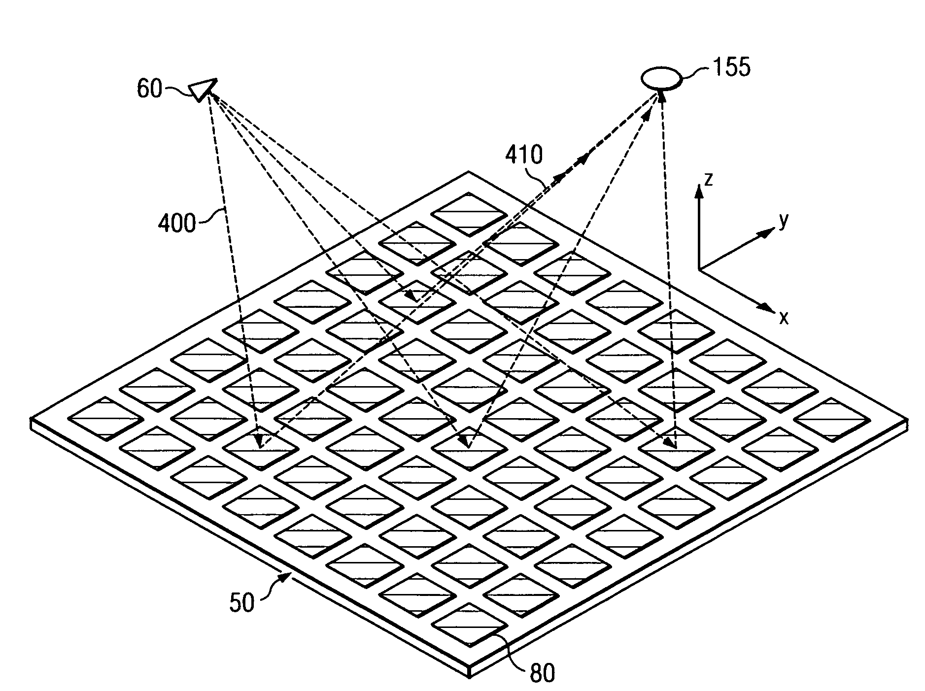
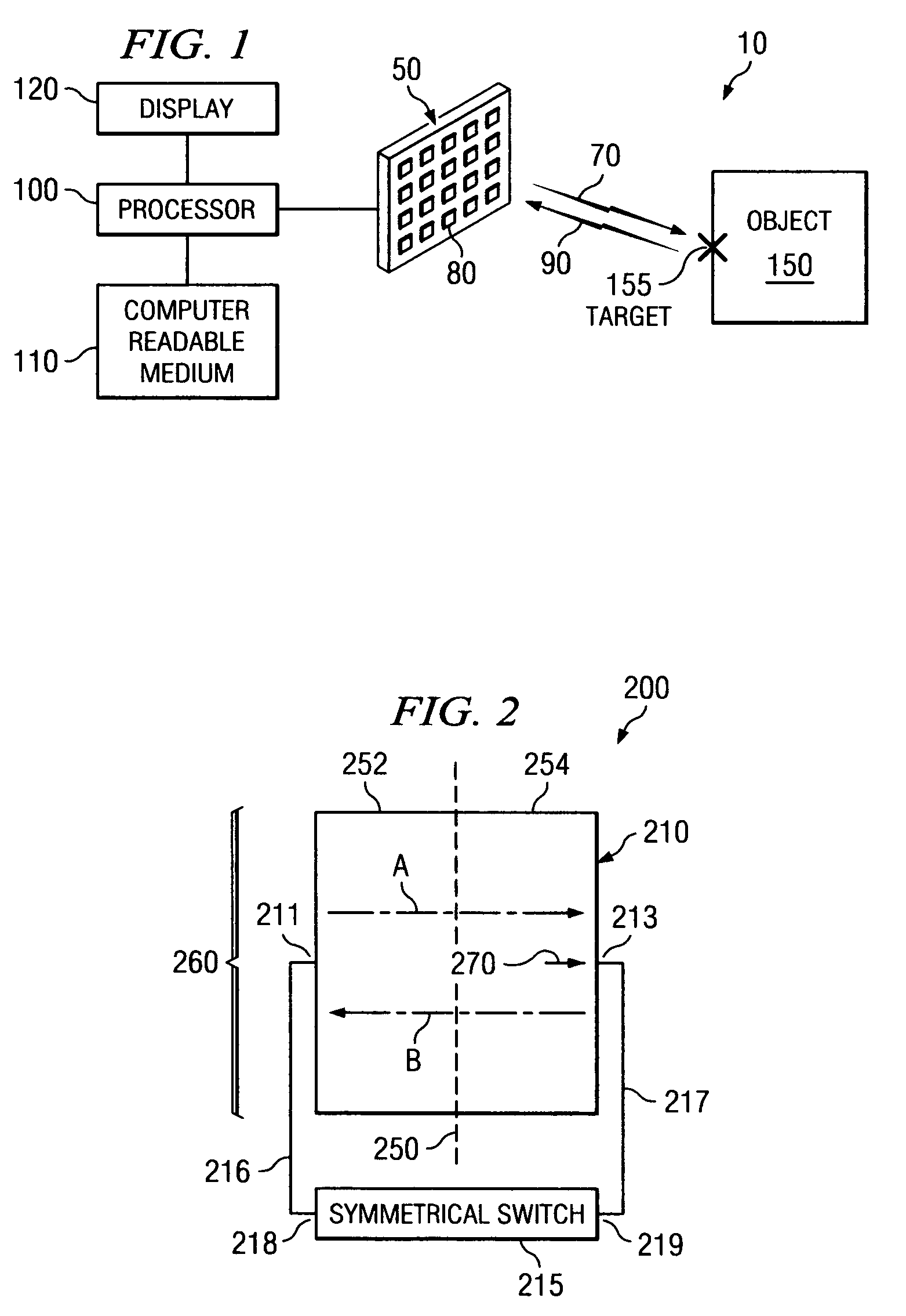
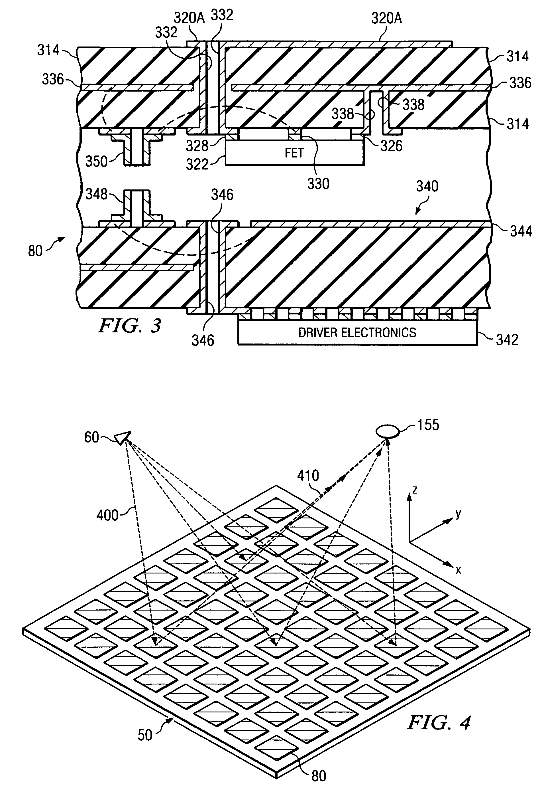
[0030]FIG. 1 is a schematic diagram of a simplified exemplary microwave imaging system 10, in accordance with embodiments of the present invention. The microwave imaging system 10 includes a one or more scanning panels 50 (only one of which is shown for convenience), each capable of transmitting microwave radiation and / or receiving microwave radiation via antenna elements 80 to capture a microwave image of an object (e.g., suitcase, human subject or any other item of interest).

[0031]In one embodiment, the scanning panel 50 includes a passive programmable reflector array composed...


PUM


Abstract

A scanning panel for use in a microwave imaging system captures a microwave image of a target using two complementary arrays of antenna elements. Each of the antenna elements in a first array is capable of being programmed with a respective phase delay to direct a transmit beam of microwave illumination toward the target in a transmit beam pattern, and each of the antenna elements in a second array is capable of receiving reflected microwave illumination reflected from the target in a receive beam in a receive beam pattern complementary to the transmit beam pattern. The microwave image of the target is formed at an intersection between the transmit beam and the receive beam.

Description

CROSS-REFERENCE TO RELATED APPLICATIONS[0001]This application is related by subject matter to U.S. patent application Ser. No. 10 / 997,422, entitled “A Device for Reflecting Electromagnetic Radiation,” U.S. patent application Ser. No. 10 / 997,583, entitled “Broadband Binary Phased Antenna,” and U.S. Pat. No. 6,965,340, entitled “System and Method for Security Inspection Using Microwave Imaging” all of which were filed on Nov. 24, 2004.[0002]This application is further related by subject matter to U.S. patent application Ser. No. 11 / 088,831, entitled “System and Method for Inspecting Transportable Items Using Microwave Imaging,” U.S. patent application Ser. No. 11 / 089,298, entitled “System and Method for Pattern Design in Microwave Programmable Arrays,” U.S. patent application Ser. No. 11 / 088,610, entitled “System and Method for Microwave Imaging Using an Interleaved Pattern in a Programmable Reflector Amy,” and U.S. patent application Ser. No. 11 / 088,830, entitled “System and Method f...

Claims


Application Information

Patent Timeline
Patent Type & Authority Patents(United States)
IPC IPC(8): H01Q15/00H01Q3/00
CPCG01S13/89H01Q3/46H01Q21/0018H01Q25/00H01Q21/22H01Q23/00H01Q21/061
Inventor LEE, GREGORY STEVENTABER, ROBERT C.BAHARAV, IZHAK
Owner AGILENT TECH INC
Why Eureka
Try Eureka