Transmission slot allocation method and map for virtual tunnels in a transmission line

Inactive Publication Date: 2007-10-16
FUJITSU LTD
View PDF35 Cites 2 Cited by
  • Summary
  • Abstract
  • Description
  • Claims
  • Application Information

AI Technical Summary

Benefits of technology

[0010]The present invention provides a transmission slot allocation method and map that substantially eliminate or reduce the disadvantages and problems associated with previous systems and methods. In particular, the map stores predefined sets of interleaved port transmission slots that can be assigned to dedicated or dynamic bandwidth traffic.
[0013]Technical advantages of the present invention include providing an improved method and map for allocating bandwidth of a transmission line to a virtual interface. In particular, port transmission slots are grouped into a plurality of hierarchical sets having interleaved port transmission slots. The hierarchical sets can be dynamically allocated to a virtual interface to provide transmission slots for any supported bandwidth. In addition, the transmission slots in each set are substantially evenly spaced throughout the transmission frame of the port. This provides minimal delay variation for both dedicated and dynamic bandwidth traffic, and for multiple virtual interfaces operating at different rates. The hierarchical sets are also sized to be equal to or only slightly larger than a supported transmission rate. As a result, allocatable bandwidth is maximized.

Problems solved by technology

As a result, such traffic typically has a high cell delay variation.

Method used


Image

  • Transmission slot allocation method and map for virtual tunnels in a transmission line
  • Transmission slot allocation method and map for virtual tunnels in a transmission line
  • Transmission slot allocation method and map for virtual tunnels in a transmission line

Examples


Embodiment Construction

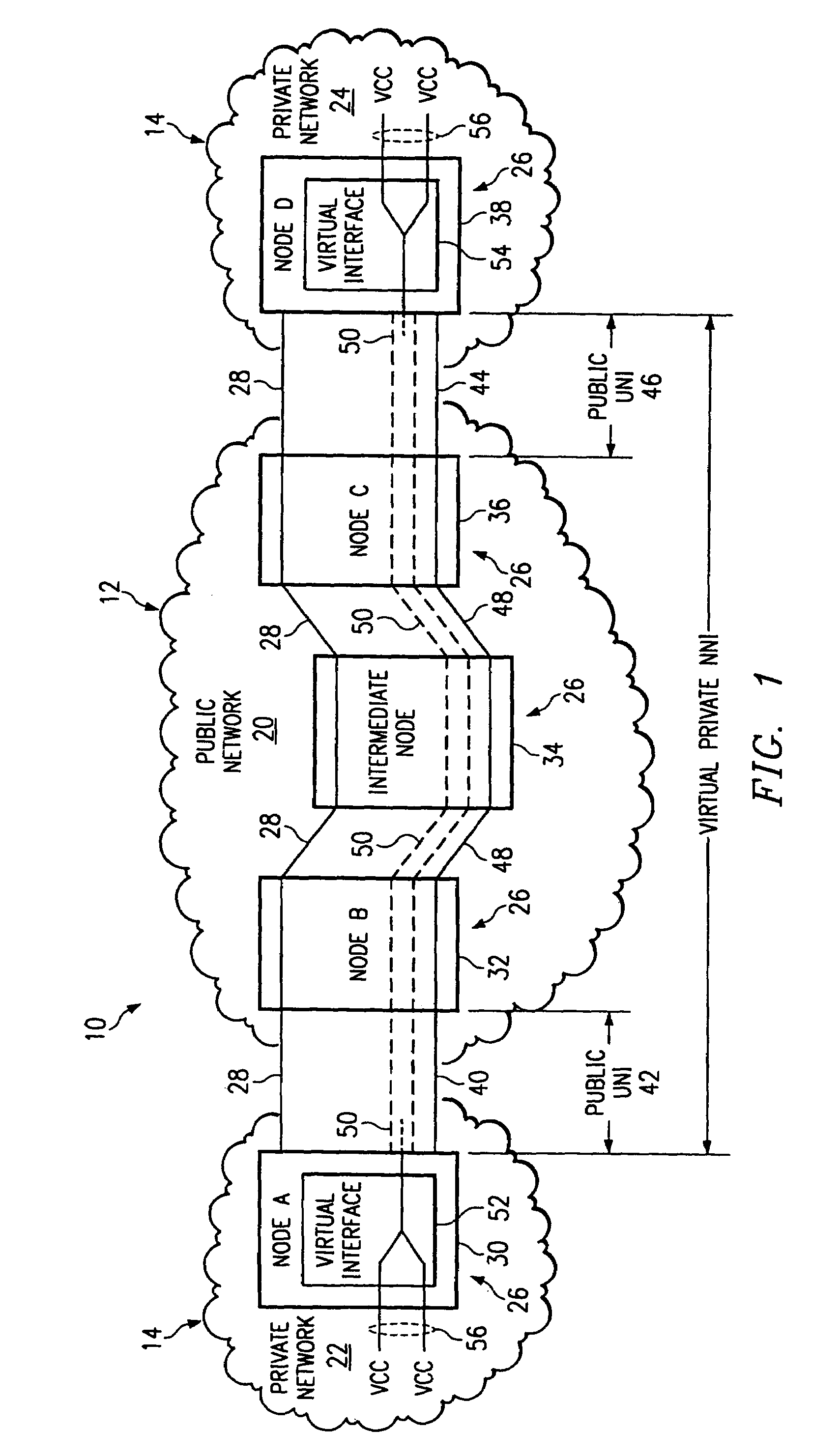
[0023]FIG. 1 illustrates a telecommunications system 10 in accordance with one embodiment of the present invention. In this embodiment, the telecommunications system 10 comprises a public portion 12 and a private portion 14 that each transmit voice, data, other suitable types of information, and / or a combination of different types of information. The public portion 12 includes a public network 20 such as the Internet. The private portion 14 includes remote private networks 22 and 24. The private networks 22 and 24 are each an Intranet or other suitable network such as a private local area network (LAN) or a private wide area network (WAN). The telecommunications system 10 may be entirely implemented in either the public network 20 or in one of the private networks 22 or 24, or may be otherwise suitably distributed between disparate networks.

[0024]Referring to FIG. 1, the telecommunications system 10 includes a plurality of nodes 26 interconnected by transmission lines 28. The nodes ...


PUM


Abstract

In accordance with one embodiment of the present invention, a map of transmission slots for a port of a network element includes a plurality of hierarchical sets of port transmission slots. The hierarchical sets include a plurality of parent sets. Each parent set has its port transmission slots divided between a plurality of child sets. The child sets include interleaved port transmission slots.

Description

CROSS-REFERENCE TO RELATED APPLICATIONS[0001]This application is a continuation of U.S. application Ser. No. 09 / 325,497, filed Jun. 3, 1999 now U.S. Pat. No. 6,665,301 and entitled “TRANSMISSION SLOT ALLOCATION METHOD AND MAP FOR VIRTUAL TUNNELS IN A TRANSMISSION LINE”.[0002]This application is related to copending U.S. application Ser. No. 09 / 997,626, filed Nov. 28, 2001 and entitled “METHOD AND SYSTEM FOR TRANSMITTING TRAFFIC IN A VIRTUAL TUNNEL OF A TRANSMISSION LINE”, which is a continuation of U.S. application Ser. No. 09 / 325,687 filed Jun. 3, 1999 and entitled “METHOD AND SYSTEM FOR TRANSMITTING TRAFFIC IN A VIRTUAL TUNNEL OF A TRANSMISSION LINE”.TECHNICAL FIELD OF THE INVENTION[0003]This invention relates generally to the field of telecommunication systems, and more particularly to a transmission slot allocation method and map for virtual tunnels in a transmission line.BACKGROUND OF THE INVENTION[0004]Telecommunications networks have traditionally been circuit-switch networks...

Claims


Application Information

Patent Timeline
IPC IPC(8): H04L12/28H04L12/56H04Q11/04
CPCH04L12/5602H04Q11/0478H04L2012/5679H04L2012/5651
Inventor WU, GUOLIANG
Owner FUJITSU LTD
Why Eureka
Try Eureka