Averaging orifice primary flow element

a primary flow element and orifice plate technology, applied in the direction of measurement devices, volume/mass flow measurement, instruments, etc., can solve the problems of increasing maintenance requirements, reducing the cost of process piping, and adding separate and additional components to the process piping with the attendant initial cos

Active Publication Date: 2007-10-23
DIETERICH STANDARD
View PDF44 Cites 36 Cited by
  • Summary
  • Abstract
  • Description
  • Claims
  • Application Information

AI Technical Summary

Benefits of technology

[0010]According to the present invention, a constrictive plate, or flow impedance device, having a plurality of variously positioned orifices is placed in a fluid-carrying conduit with static pressure measurement taken on the upstream and downstream sides of the plate. Each of the plurality of orifices will conduct a part of the total fluid flow within the conduit. According to Bernoulli's theorem, the velocity of the fluid through each of the orifices will increase, and the static fluid pressure on the downstream side of the constricting plate that is attributable to each of the separate orifices will be averaged within the fluid to provide an average downstream static pressure. The average downstream static pressure is compared with the upstream static pressure to provide an average differential pressure for whatever velocity profile is presented to the multiple orifice plate, resulting in an accurate measurement of the rate of fluid flow in the pipe.
[0011]Integrally incorporating the multiple orifice plate into the central opening of an annular ring with intermediate upstream and downstream static pressure measuring ports disposed within the ring, provides added simplicity to the primary flow element. This simplicity is further enhanced when the annular ring is provided with a projecting stem that is capable of conducting the sensed differential pressure to other flow processing accessories mounted on the stem.

Problems solved by technology

While the accuracy of such devices is good for long runs of pipe, orifice plate flow meters suffer the disadvantage of poor performance when placed in short pipe runs that follow a flow disturbance created by upstream apparatus, such as an elbow, expander, reducer, valve or other discontinuity.
When an upstream pipe fitting or other device skews the velocity profile, the pressures measured at the orifice flow meter pressure taps is in error.
Flow straighteners, conditioners, computers and piezometers are moderately effective to properly condition the velocity profile for introduction to an orifice plate flowmeter, or average the asymmetric velocity of the flow, but have the disadvantage of adding separate and additional components to the process piping with the attendant initial cost, pressure drop in the fluid, and increased maintenance requirements.

Method used


Image

  • Averaging orifice primary flow element
  • Averaging orifice primary flow element
  • Averaging orifice primary flow element

Examples


Embodiment Construction

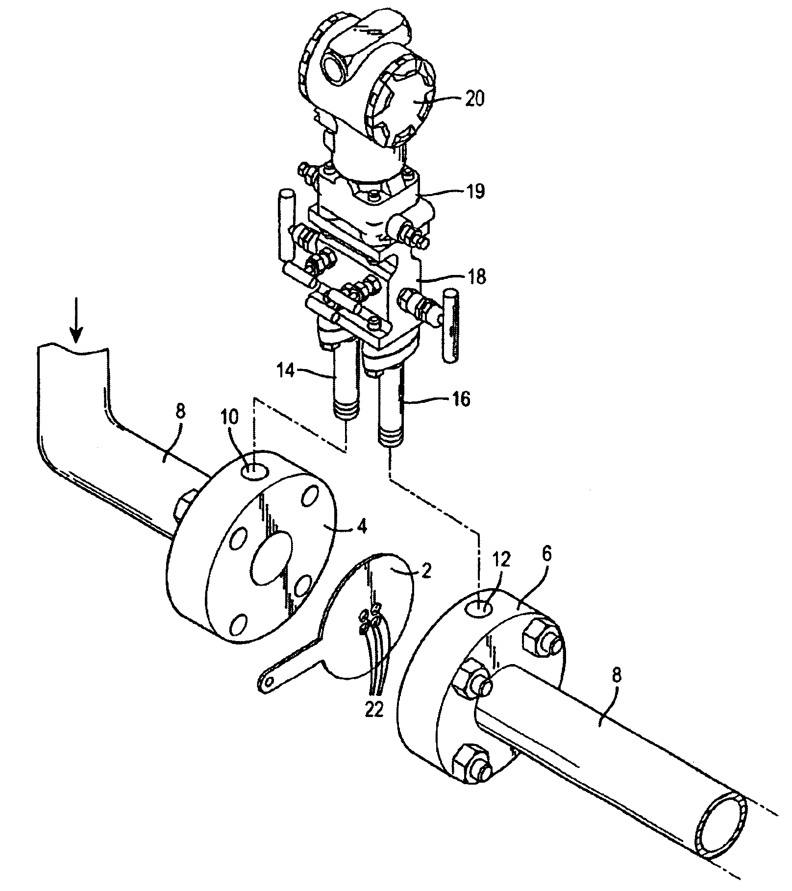
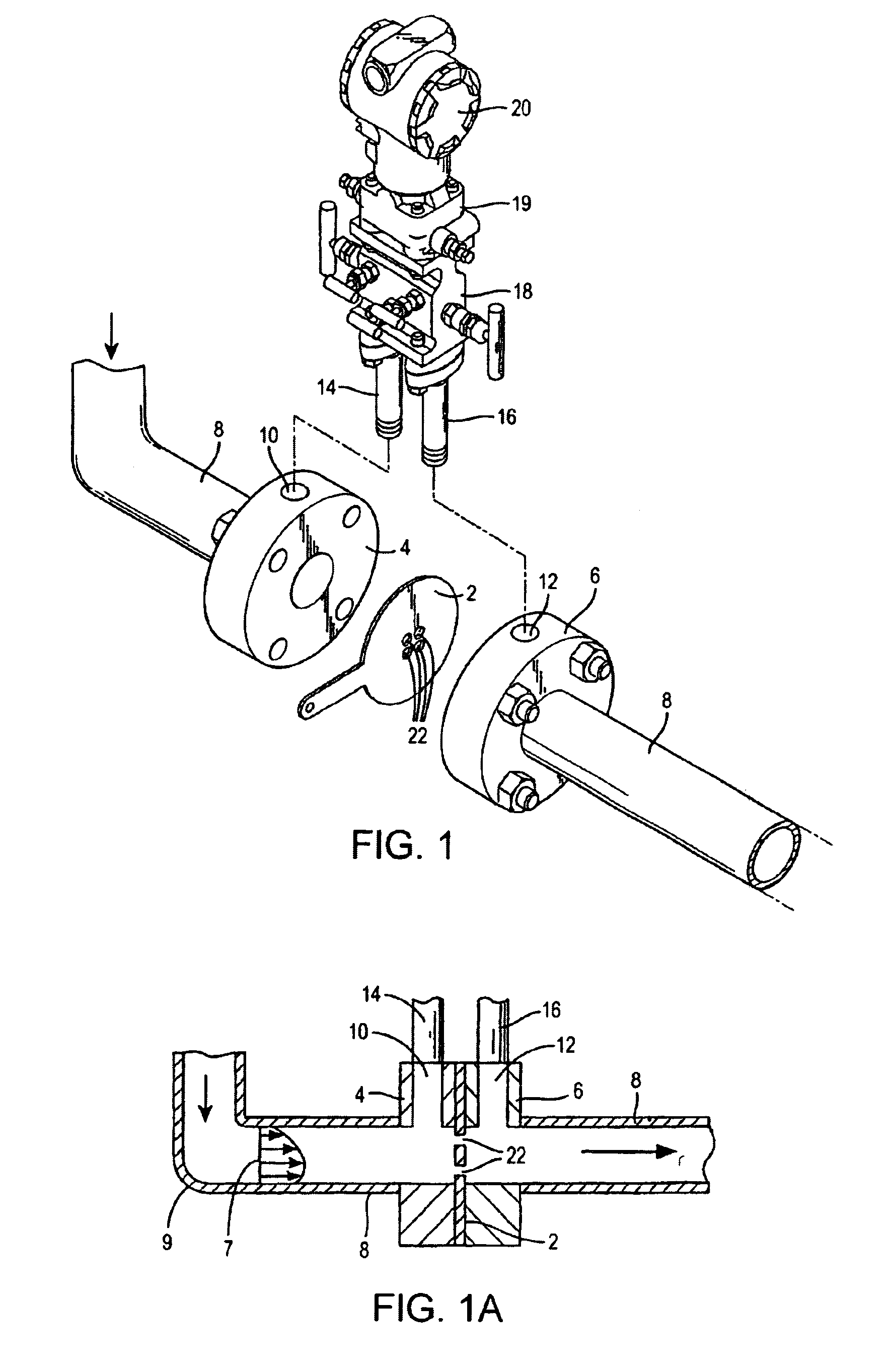
[0022]A simplified version of the present invention is shown in FIGS. 1 and 1A. An averaging orifice primary flow element 2 is positioned between two opposing mounting flanges 4 and 6 fixed to the ends of a fluid-carrying conduit 8 just below an elbow 9 where the velocity profile 7 is skewed. Each of the mounting flanges contain a radially extending pressure sensing port 10 and 12 that communicate with the fluid flowing in the pipe and are respectively connected through conduits 14 and 16 to a valve manifold 18 and into a pressure transducer 19. An electrical signal that represents the sensed differential pressure between the ports 10 and 12 is transmitted by transmitter 20 to a processing unit (not shown).

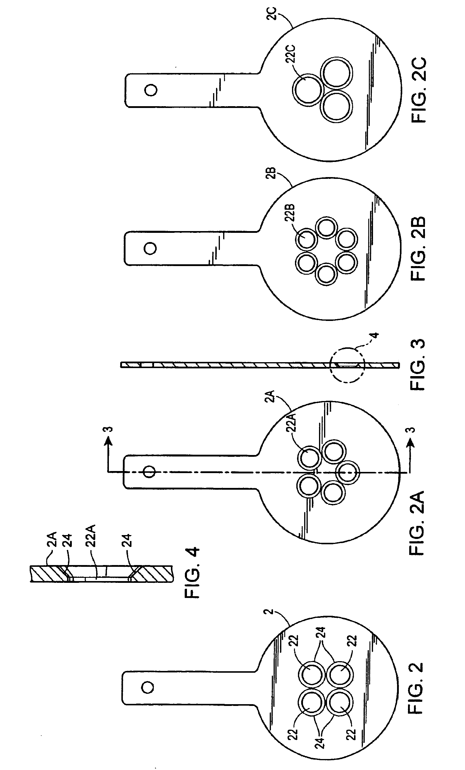
[0023]The primary flow element 2, also shown in FIG. 2, comprises a circular plate having four apertures 22 symmetrically arranged around the center of the plate 2. The center of the flow element plate 2 is positioned coaxially with the longitudinal centerline of the pipe 8. The p...


PUM


Abstract

A process flow device that includes a self-averaging orifice plate type of primary flow element for measuring, by a differential pressure process, the volumetric rate of fluid flow at a point in a fluid carrying conduit where the velocity profile of the fluid is asymmetric with respect to the longitudinal axis of the conduit. The improved flow element comprises a planar flow-impeding plate disposed transversely across the interior of the conduit and perpendicular to the longitudinal axis thereof. The plate includes at least three circular apertures eccentrically disposed with respect to the longitudinal axis of the conduit to create static pressure averaging on the downstream side of the plate. Upstream and downstream static pressure sensing ports are respectively provided on opposite sides of the flow impeding plate.

Description

FIELD OF THE INVENTION[0001]The present invention relates generally to a process flow device that includes a self-averaging orifice plate type of primary flow element for measuring, by a differential pressure process, the volumetric rate of fluid flow at a point in a fluid carrying conduit where the velocity profile of the fluid is asymmetric with respect to the longitudinal axis of the conduit.BACKGROUND OF THE INVENTION[0002]Orifice plate flow meters having a single centered opening in a plate constriction that is disposed diametrically within a fluid-carrying pipe, with differential pressure measurement means on the upstream and downstream sides of the constriction, have been in existence for a long period of time. While the accuracy of such devices is good for long runs of pipe, orifice plate flow meters suffer the disadvantage of poor performance when placed in short pipe runs that follow a flow disturbance created by upstream apparatus, such as an elbow, expander, reducer, val...

Claims


Application Information

Patent Timeline
Patent Type & Authority Patents(United States)
IPC IPC(8): G01F1/37G01F1/00G01F1/34G01F1/42G01F1/46
CPCG01F1/34G01F1/46G01F1/42
Inventor ORLESKIE, CHARLES THEODOREBEACHEY, TERRY XEN
Owner DIETERICH STANDARD
Why Eureka
Try Eureka