Light equalizing structure of backlight modules

a backlight module and reflective panel technology, applied in the field of light reflection technology for backlight modules, can solve problems such as difficult to anticipate, and achieve the effect of uniform brightness

Inactive Publication Date: 2007-10-23
K-BRIDGE ELECTRONICS CO LTD
View PDF6 Cites 7 Cited by
  • Summary
  • Abstract
  • Description
  • Claims
  • Application Information

AI Technical Summary

Benefits of technology

[0006]It is a primary objective of the present invention to provide a light equalizing structure of backlight modules, which installs a plurality of reflective sections on a reflective panel of a backlight module for reflecting the light emitted by a light source towards a panel assembly, and each reflective section keeps a predetermined distance from the light source. The height of each reflective section is directly proportional to the distance of the reflective section from its light source. In other words, there is a specific height difference between every two adjacent reflective sections, so that the light emitted from different angles of the light source can be reflected evenly from each reflective section on the reflective panel towards the panel assembly to achieve the effect of producing even brightness for each section of the panel assembly.

Problems solved by technology

Therefore, it is difficult to anticipate that the light emitted from the light sources can be reflected evenly towards every section of the panel assembly 10′.

Method used


Image

  • Light equalizing structure of backlight modules
  • Light equalizing structure of backlight modules
  • Light equalizing structure of backlight modules

Examples


Embodiment Construction

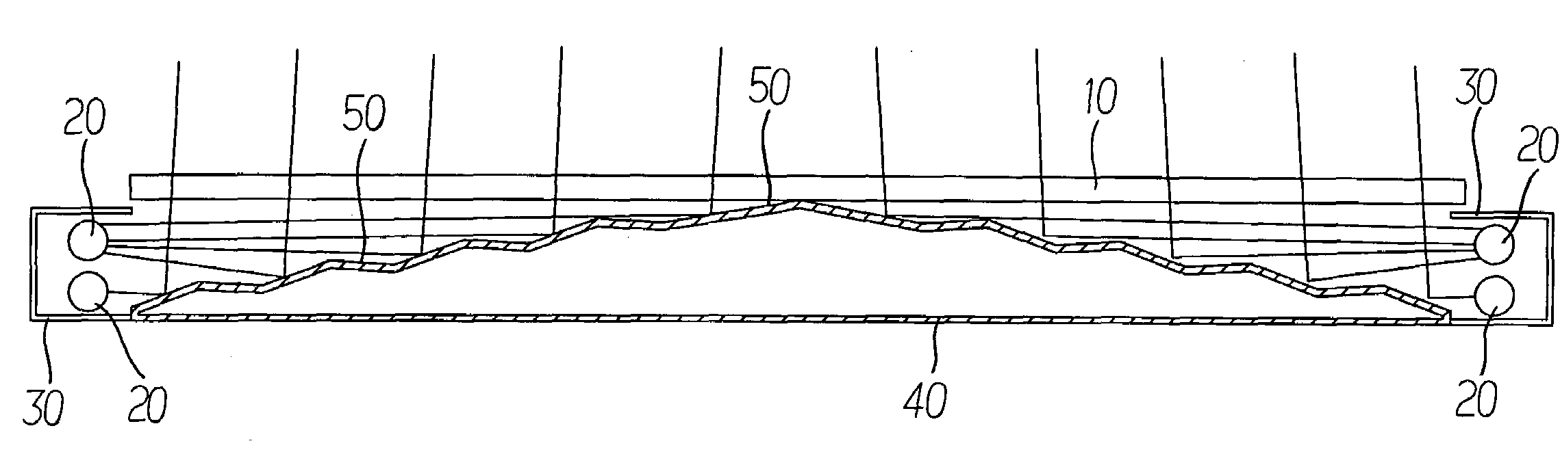
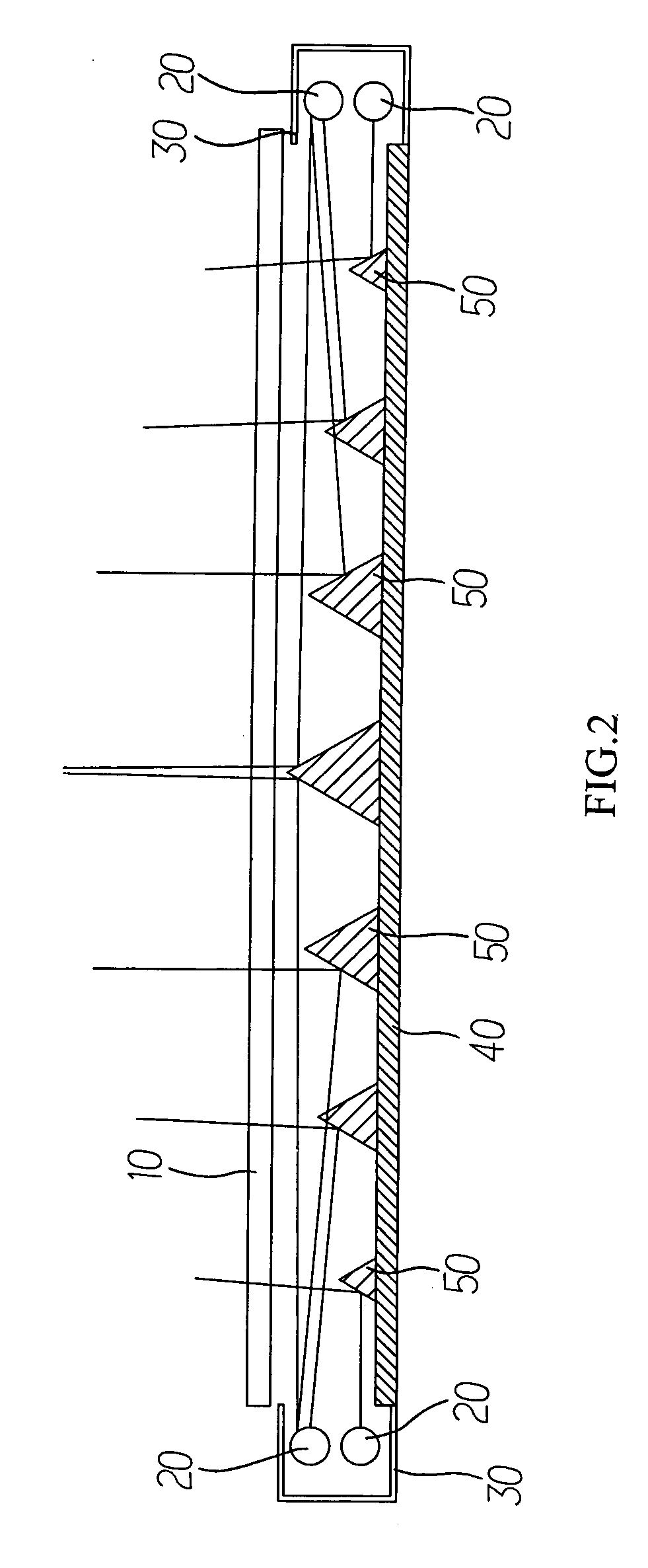
[0010]Referring to FIG. 2, a light equalizing structure of the present invention is illustrated. The assembly of the light equalizing structure as shown in FIG. 2 comprises a plurality of reflective sections 50 on a reflective panel 40 of a backlight module for reflecting the light emitted by a light source 20 towards a panel assembly 10, and each reflective section 50 keeps a predetermined distance from the light source 20. The height of each reflective section 50 is directly proportional to the distance from its light source 20. In other words, there is a specific height difference between every two adjacent reflective sections 50.

[0011]In actual practices, the whole backlight module comprises at least one light source 20 disposed on a side of a panel assembly 10 and a reflective hood sheltering an external side of the light source 20. With such reflective hood 30, the light of the light source 20 is reflected towards the internal side of the panel assembly 10. A reflective panel ...


PUM


Abstract

A light equalizing structure installs a plurality of reflective sections on a reflective panel of a backlight module for reflecting the light emitted by a light source towards a panel assembly, and each reflective section keeps a predetermined distance from the light source. The height of each reflective section is directly proportional to the distance from its light source. In other words, there is a predetermined height difference for every two adjacent reflective sections, so that the light emitted from different angles of the light source can be reflected evenly from each reflective section on the reflective panel towards the panel assembly to achieve the effect of providing even brightness for each section of the panel assembly.

Description

BACKGROUND OF THE INVENTION[0001]1. Field of the Invention[0002]The present invention generally relates to a light reflection technology for backlight modules, and more specifically to an improved light equalizing structure of a reflective panel of a backlight module capable of producing an even brightness for each section of the panel assembly of the backlight module.[0003]2. Description of the Related Art[0004]Referring to FIG. 1, a cross-sectional view of a backlight module structure used for liquid crystal displays is shown. The backlight module structure comprises at least one light source 20′ disposed on a side of a panel assembly 10′, and a reflective hood 30′ sheltering an external side of the light source 20′. With such reflective hood 30′, the light of the light source 20′ is reflected towards the internal side of the panel assembly 10′. In particular, a reflective panel 40′ is installed at the bottom of another panel assembly 10′ of the whole backlight module for reflecti...

Claims


Application Information

Patent Timeline
Patent Type & Authority Patents(United States)
IPC IPC(8): F21V7/04
CPCG02B6/0038G02F1/133615G02B6/0061G02B5/045G02B6/0055
Inventor TSENG, WEN-PAO
Owner K-BRIDGE ELECTRONICS CO LTD
Why Eureka
Try Eureka