Supporting structure of fixed contact terminals

a technology of fixed contact terminals and supporting structures, which is applied in the direction of contacts, electromagnetic relay details, relays, etc., can solve the problems of short circuit, deterioration of insulation performance, short circuit, etc., and achieve the effect of easy manufacturing of molds

Active Publication Date: 2007-10-23
ORMON CORP
View PDF5 Cites 26 Cited by
  • Summary
  • Abstract
  • Description
  • Claims
  • Application Information

AI Technical Summary

Benefits of technology

[0010]According to the invention, even when scattered powder is generated when the movable contacts contact with and separate from the fixed contacts, the scattered powders can be prevented from attaching to the corner of the insulating groove having a downwardly-broaden cross section. Therefore, even when the scattered powders are scattered around, no continuous short circuit is formed on the surface of the base, a desired insulation performance can be kept for a long time, and a supporting structure of a contact piece with a long lifespan can be obtained.
[0012]According to the embodiment, since the cross section of the insulation groove is formed by orthogonal lines, a mold can be manufactured easily.

Problems solved by technology

In the above-mentioned supporting structure of the fixed contact terminal 2 and the movable contact terminal 3, however, scattered powder of the contacts caused at the time of turning on and off the contacts is attached on the top surface of the base 1 between the contact terminals 2 and 3, which causes a short circuit and deteriorates the insulation performance.
In the above-mentioned supporting structure of the contact terminals, however, scattered powder is attached not only to the upper surface of the base 1 between the contact terminals 2 and 3 but also to the inner surface of the groove 6, which causes a short circuit and disturbs a desired insulation performance for a long time.

Method used


Image

  • Supporting structure of fixed contact terminals
  • Supporting structure of fixed contact terminals
  • Supporting structure of fixed contact terminals

Examples


Embodiment Construction

[0033]A preferred embodiment of the invention will be described according to the accompanying drawings of FIG. 1 to FIG. 18.

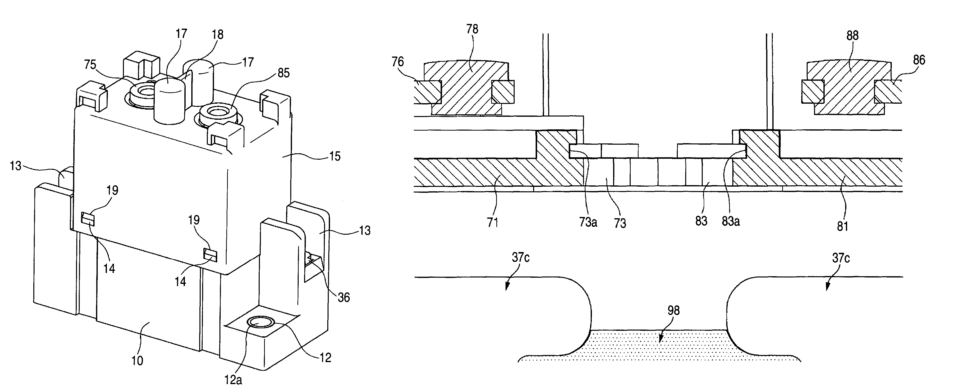
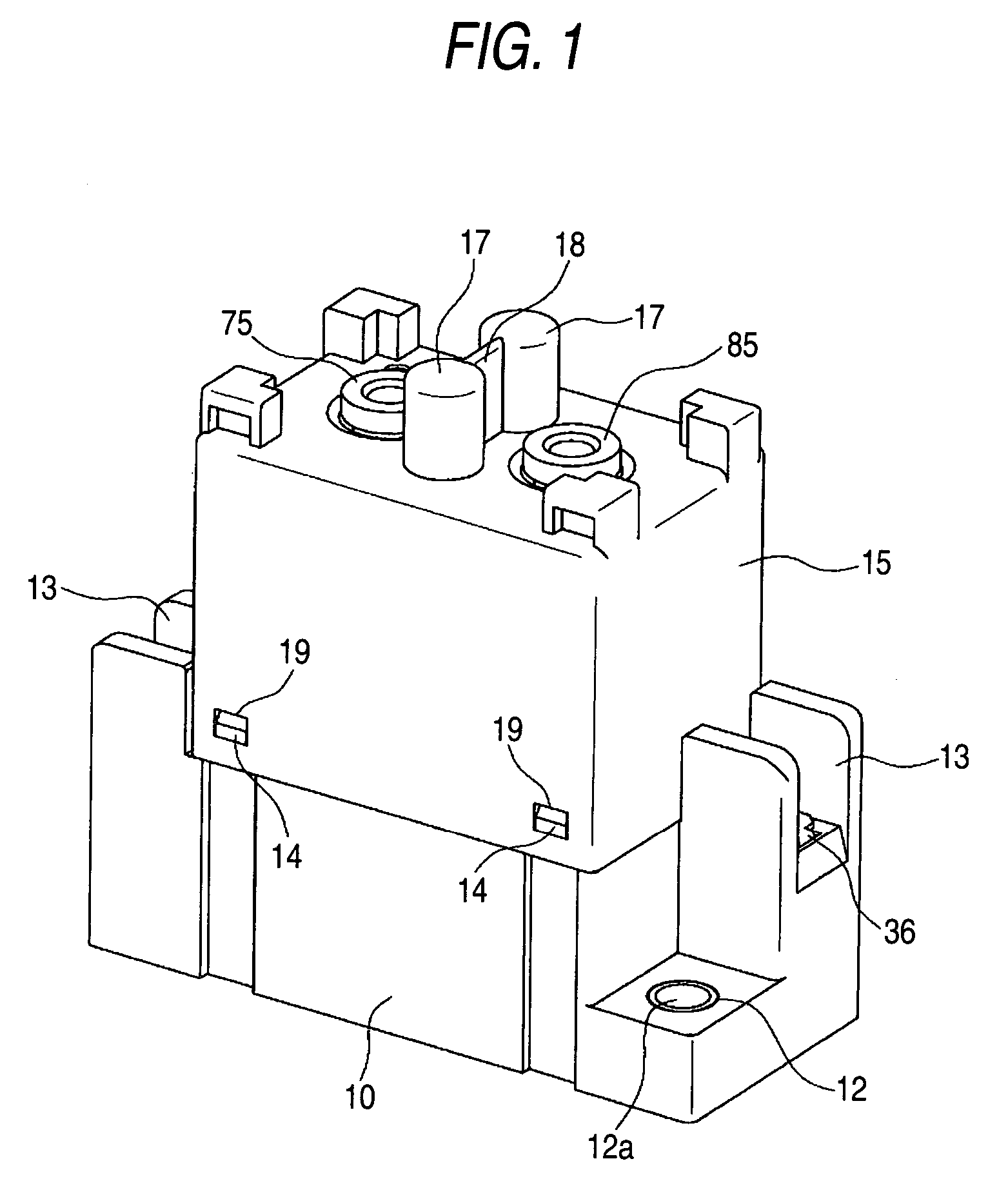
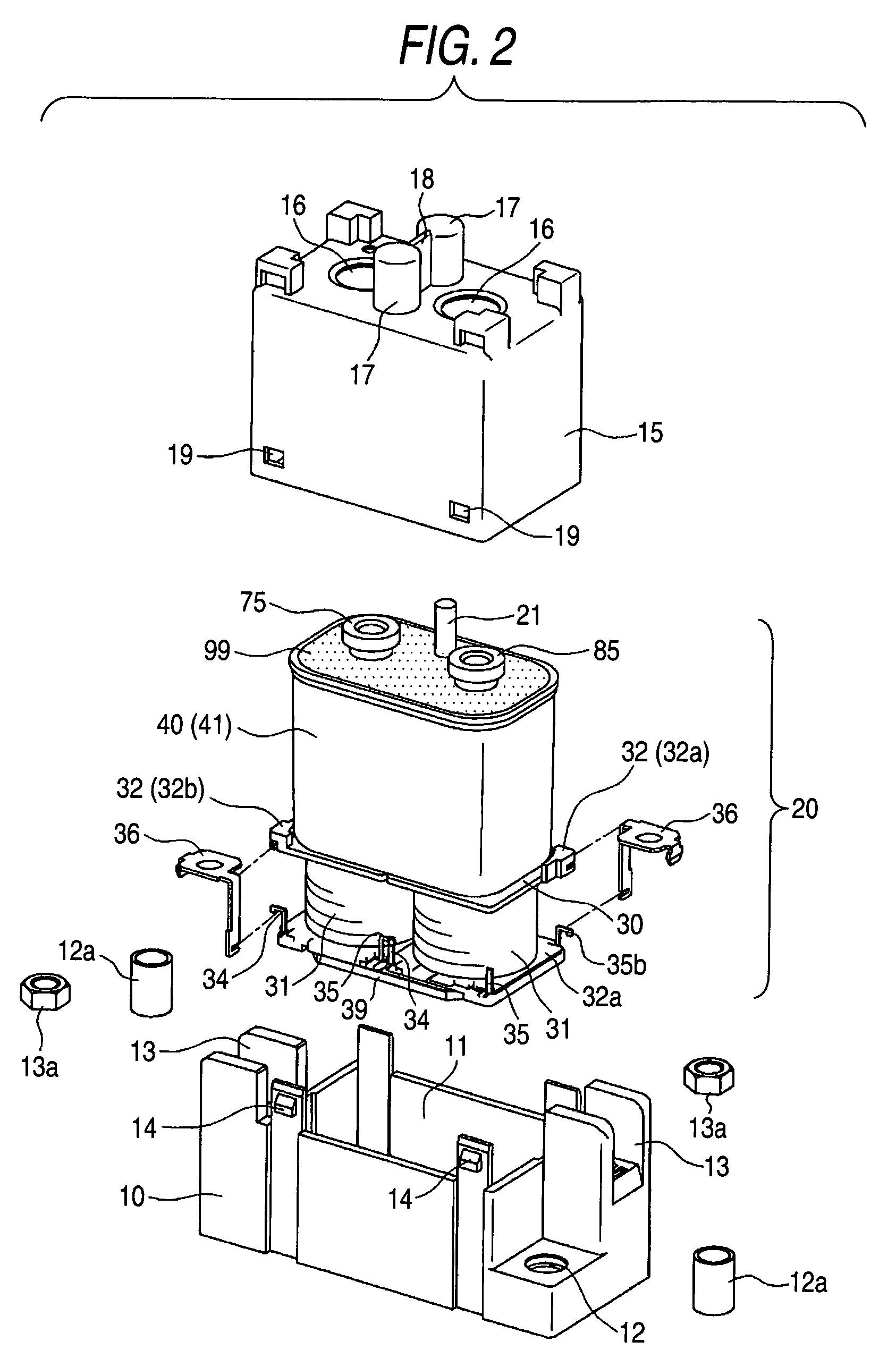
[0034]This description will be made in the case where this embodiment is used for a relay for switching a direct current load, and as illustrated in FIG. 1 and FIG. 2, the main body of a relay 20 is housed in a space integrally formed by a box case 10 and a box cover 15.

[0035]The box case 10 has a recessed portion 11 capable of housing an electromagnetic block 30 described later, and it is provided with through holes 12 for fixing respectively at two corners positioned on one of the diagonal lines and with jointing concaves 13 at the remaining two corners, as illustrated in FIG. 2. A reinforcing cylinder 12a is inserted into each of the through holes 12 and a joint nut 13a is inserted into each of the jointing concaves 13.

[0036]The box cover 15 can be fixed to the box case 10 and it has a shape capable of housing a sealing case block 40 described later. The box...


PUM


Abstract

In the supporting structure of fixed contact terminals, a pair of fixed contact terminals with respective fixed contacts provided on their free ends are supported by fixed contact bases and the both ends of a movable contact piece contact with and separate from the pair of the fixed contacts. Cut-off grooves are provided on the surfaces of the fixed contact bases at each position near the fixed contacts, and they are formed in a converted T shape on a cross section, partitioning the pair of fixed contact terminals.

Description

BACKGROUND OF THE INVENTION[0001]1. Field of the Invention[0002]The present invention relates to a supporting structure of fixed contact terminals, and more particularly to a supporting structure of the fixed contact terminals concerned with an electromagnetic relay.[0003]2. Description of the Related Art[0004]As the supporting structure of the fixed contact terminals, there has been, for example, that one in which a fixed contact terminal 2 and a movable contact terminal 3 stand on a base 1 in an opposed way and a fixed contact point 4 and a movable contact point 5 are provided in the both terminals at the respective upper portions on their opposed surfaces in a removable way, as illustrated in FIG. 19.[0005]In the above-mentioned supporting structure of the fixed contact terminal 2 and the movable contact terminal 3, however, scattered powder of the contacts caused at the time of turning on and off the contacts is attached on the top surface of the base 1 between the contact termi...

Claims


Application Information

Patent Timeline
Patent Type & Authority Patents(United States)
IPC IPC(8): H01H67/02H01H50/14H01H1/00H01H1/66H01H9/02H01H9/48
CPCH01H9/02H01H9/48H01H2050/025H01H2050/028
Inventor NISHIDA, TAKESHIMASUI, YASUYUKIMIYASAKA, TAKESHI
Owner ORMON CORP
Why Eureka
Try Eureka