Method for configuring a communication network, related network architecture and computer program product therefor

a communication network and network architecture technology, applied in the field of communication networks, can solve the problems of inability to achieve the optimal tilt angle set for a given antenna at a given time, and the prior art arrangement still suffers from a number of intrinsic drawbacks, so as to achieve the effect of improving the performance of the whole network and maximising the traffic ratio

Inactive Publication Date: 2007-10-23
PIRELLI & C +1
View PDF8 Cites 96 Cited by
  • Summary
  • Abstract
  • Description
  • Claims
  • Application Information

AI Technical Summary

Benefits of technology

[0023]In second generation systems such as GSM, the possibility of controlling and limiting the interference level is a key parameter in order to be able to cover as a high number of users as possible while ensuring a good quality of service without changing the number of channels available.
[0038]A preferred embodiment of the invention analyses the traffic requirements of the whole area served and derives therefrom an optimum radiation diagram for configuring the respective antenna. Preferably, the results are optimised in terms of maximising the ratio of the traffic offered and collected in the coverage area to the attenuation experienced by the signal in the specific direction pointing to the “pixel” of the area covered being considered. Each single antenna can thus be configured for best serving those users that are “reachable” in terms of electromagnetic field with the minimum energy allocation in terms of signal irradiated, which in turn is a source of potentially interference with the other antennas included in the network. The search for the optimal configuration of the radiation diagram can be repeated for all the antennas in the network considered, by using as a final result an optimal integrated configuration related to all the radiating systems included in the network.
[0039]The arrangement described herein also lends itself to be possibly used in reconfiguring an existing network: specifically a number of areas operating under critical conditions may be identified and one or more reconfigurable antennas substituted for existing “fixed” antennas in order to solve the problems existing in the critical areas and possibly improve the performance of the whole network.

Problems solved by technology

Even though going in the direction of providing a network wherein the characteristics of the various antennas can be dynamically adapted to different operating conditions, such prior art arrangements still suffer from a number of intrinsic drawbacks.
Such an optimisation process must be repeated for each antenna, with the possibility that the optimum tilt angle set for a given antenna at a given time may no longer be optimum after the tilt angles of one or more neighbouring antennas have been optimised in turn.

Method used


Image

  • Method for configuring a communication network, related network architecture and computer program product therefor
  • Method for configuring a communication network, related network architecture and computer program product therefor
  • Method for configuring a communication network, related network architecture and computer program product therefor

Examples


Embodiment Construction

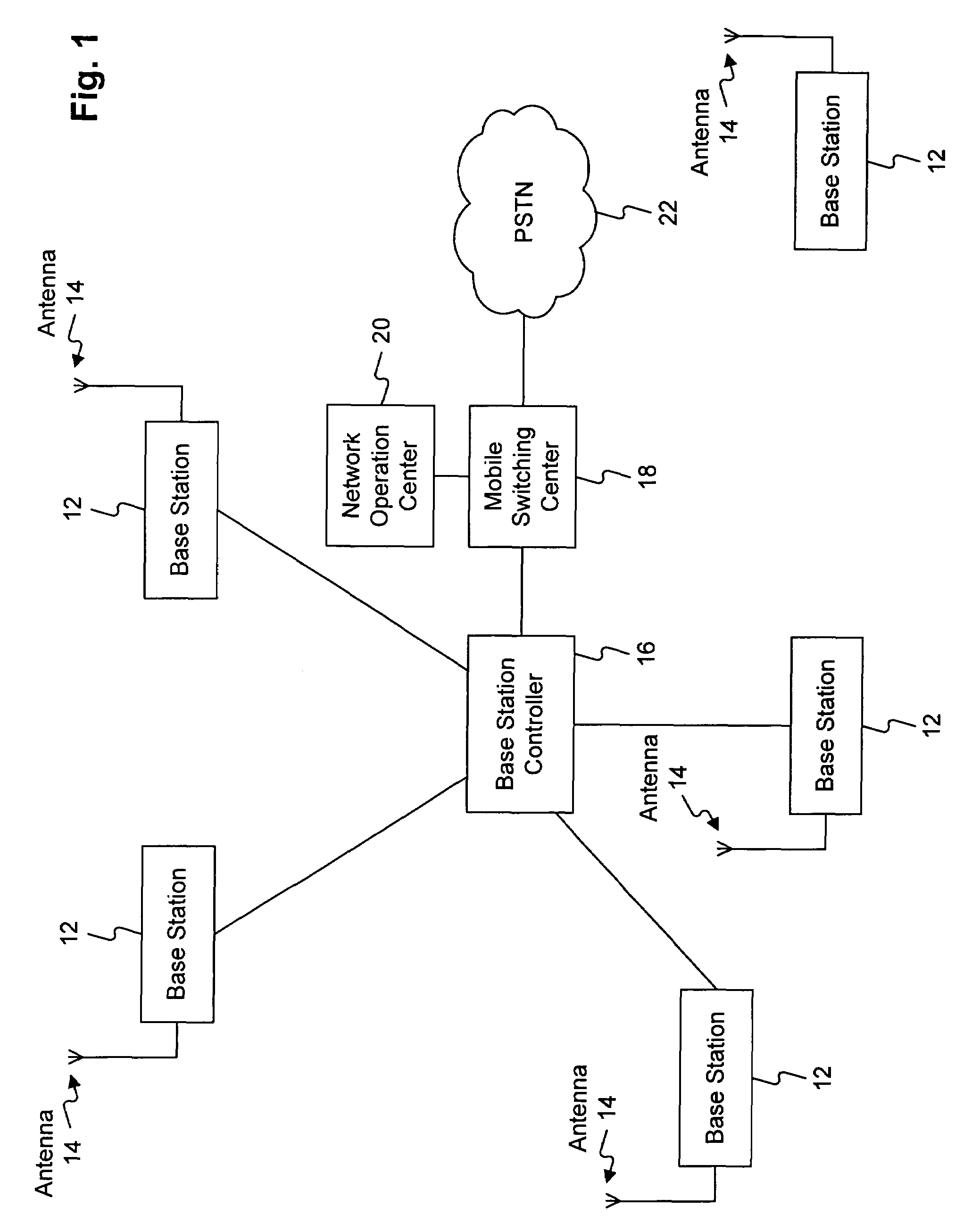
[0047]In FIG. 1, reference 10 indicates as a whole a telecommunication system such as a mobile communication network according to any known standard.

[0048]A GSM network or a UMTS network may be considered as examples of the so-called second and third generations (3G) of such systems. The invention is however applicable to any type of communication networks, even without limitation to a cellular communication network.

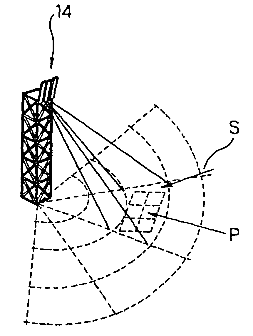
[0049]The schematic representation of FIG. 1 exclusively represents the “fixed” part of the network, excluding the mobile terminals. The fixed part of the network shown includes a plurality of base stations 12 each having associated therewith at least one respective radiation system such as an antenna 14.

[0050]Each or at least a part of the antennas 14 shown are of the kind whose radiation diagram may be selectively adjusted, thus making it possible to modify the radiation diagram of the antenna by means of electrical signals provided by the respective base station 12 de...


PUM


Abstract

A communication network includes a plurality of antennas and includes among the antennas at least one reconfigurable antenna adapted to serve communication traffic in a respective coverage area, the reconfigurable antenna having a radiation diagram exhibiting a plurality of selectively adjustable gain values for a set of directions, each direction in the set defining a propagation path between the antenna and a portion of the coverage area, determining, for each direction in the set, at least one value of communication traffic and at least one attenuation value over the propagation path, and selectively and independently alloting to each direction in the set a respective gain value as a function of at least one of the value of communication traffic and the attenuation value determined for that direction. The arrangement is adapted for use in communication networks such as second and third generation mobile communication networks employing electrically controllable antennas.

Description

CROSS REFERENCE TO RELATED APPLICATION[0001]This application is a national phase application based on PCT / EP2003 / 006800, filed Jun. 27, 2003, the content of which is incorporated herein by reference.FIELD OF THE INVENTION[0002]The present invention relates to communication networks and was developed by paying specific attention to the possible application in configuring cellular networks and similar communication networks including antennas with respective areas of coverage (in transmission and / or reception).[0003]As used herein, “configuring” will generally apply both to planning networks to be deployed and to adjusting / optimising already existing networks.DESCRIPTION OF THE RELATED ART[0004]Research in the area of telecommunications and related technological development over the recent years had led to the possibility of designing and manufacturing radiating systems (i.e. antennas / aerials) adapted to modify their propagation characteristics.[0005]Specifically, in addition to conve...

Claims


Application Information

Patent Timeline
Patent Type & Authority Patents(United States)
IPC IPC(8): H04M1/00H04B7/005H04W16/18H04W16/24H04W16/28H04W52/42
CPCH04W16/18H04W52/42H04W16/28H04W16/24H01Q3/2605
Inventor FERRATO, MARCOGIOVANARDI, ENRICOSTOLA, LORIS PAOLODELL'ANNA, VALERIALA PIANA, ALESSANDRO
Owner PIRELLI & C
Why Eureka
Try Eureka