Cigarette maker

Inactive Publication Date: 2007-10-30
GD SPA
View PDF4 Cites 2 Cited by
  • Summary
  • Abstract
  • Description
  • Claims
  • Application Information

AI Technical Summary

Problems solved by technology

In addition, it is provenly difficult to achieve a uniform distribution of the reclaimed tobacco internally of the descent channel.
Any such lack of uniform distribution brings notable d

Method used


Image

  • Cigarette maker
  • Cigarette maker
  • Cigarette maker

Examples


Embodiment Construction

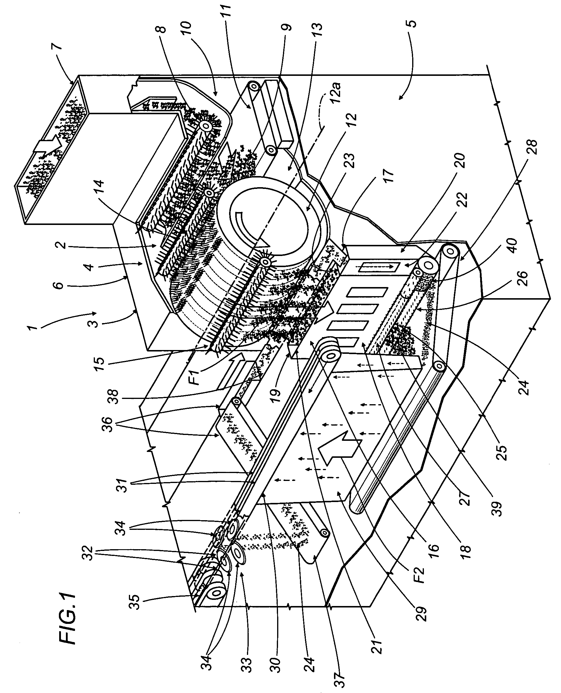
[0016]Referring to FIG. 1 of the drawings, 1 denotes the infeed portion of a cigarette maker, in its entirety, comprising a feed unit 2 by which a mass of shredded tobacco is formed into a continuous flow of tobacco particles. The components of the feed unit 2 are housed in a vertically extending enclosure 3 delimited uppermost by a horizontal wall 4 and on either side by two vertical walls 5 and 6.

[0017]The infeed portion 1 presents an inlet duct 7 extending upward from the horizontal wall 4, and below the duct, internally of the enclosure 3, a power driven toothed roller 8 by which the shredded tobacco 9 is directed down into a lower chamber 10 delimited at the bottom by a conveyor belt 11.

[0018]The chamber 10 accommodates a carding roller 12 rotatable about an axis 12a transverse to the side walls 5 and 6, forming part of a carding unit 13 and positioned adjacent to the downstream end of the belt 11. In addition to the carding roller 12, the unit 13 comprises a proportioning roll...


PUM


Abstract

In a cigarette maker comprising a descent channel filled with shredded tobacco by a carding unit and with reclaimed tobacco by a conveyor, the shredded tobacco and the reclaimed tobacco are taken up and transferred by a toothed unit toward an ascent channel, from where both are attracted onto a belt by suction and formed into a continuous stream; the descent channel is split into two distinct portions serving respectively to admit the shredded tobacco and the reclaimed tobacco, whilst the toothed unit comprises a first and a second roller positioned to take up the shredded tobacco and reclaimed tobacco and operating in conjunction with respective impeller rollers.

Description

BACKGROUND OF THE INVENTION[0001]The present invention relates to a cigarette maker.[0002]The prior art embraces cigarette making machines comprising an infeed chamber from which shredded tobacco is taken up by a carding unit and directed into a descending channel.[0003]At the bottom end of the descent channel, the tobacco is transferred by a toothed outfeed unit onto a feed conveyor and then carried by this same conveyor toward the bottom end of an ascending outfeed channel. The top end of the ascent channel is enclosed by a further conveyor consisting in an air-permeable, aspirating belt loop such as will attract the tobacco, rising through the ascent channel as a continuous flow of divided particles, and cause it to form gradually into a continuous stream of filler.[0004]The stream of tobacco forming thus externally of the ascent channel is directed by the aspirating belt loop through a trimming station of which the function is to reduce the stream to a predetermined and uniform ...

Claims


Application Information

Patent Timeline
IPC IPC(8): A24B7/14A24B1/02A24B3/06A24C1/02A24C5/39A24C5/02
CPCA24C5/394A24C5/39
Inventor MENGOLI, FAUSTOSARTONI, MASSIMODRAGHETTI, FIORENZO
Owner GD SPA
Why Eureka
Try Eureka