Eureka AIR delivers breakthrough ideas for toughest innovation challenges, trusted by R&D personnel around the world.

Method and apparatus for determining and setting material release mechanism timing for a material feed mechanism

Inactive Publication Date: 2007-10-30
VAMCO INT
View PDF24 Cites 0 Cited by
  • Summary
  • Abstract
  • Description
  • Claims
  • Application Information

AI Technical Summary

Benefits of technology

[0010]It is, therefore, an object of the present invention to provide a method for determining the correct timing of the material release mechanism. It is another object of the present invention to provide a method for setting the correct timing of the material release mechanism. It is a further object of the present invention to provide an automated system for accurately determining release mechanism timing. It is a still further object of the present invention to provide a method and apparatus that is capable of disengaging contact with a material immediately prior to engagement by an alignment device.

Problems solved by technology

The timing of the release function of the material feed mechanism is critical, as premature release may allow the material to move out of position too far for the pilot positioning pin to be effective.
This may cause hole deformation with resulting improperly positioned material.
This improperly positioned material will cause the manufacture of malformed parts and can damage the pilot positioning pin as well as the die set.
However, no technology exists for determining the precise press slide or press mechanism position when the alignment device contacts the material and the material gripping mechanism release should occur.
Determining the precise point in the press stroke when the material feed mechanism should release its grip on the strip material is difficult due to two primary problems.
First, the alignment device is typically located in a position which makes it difficult or impossible to visually inspect.
Second, the nature of a flywheel driven mechanical stamping press makes it difficult to precisely position the press slide in small increments.
This causes a motion that is very erratic and makes it difficult to precisely position the press slide, in order to verify the correct position of the alignment device relative to the strip material.

Method used


Image

  • Method and apparatus for determining and setting material release mechanism timing for a material feed mechanism
  • Method and apparatus for determining and setting material release mechanism timing for a material feed mechanism
  • Method and apparatus for determining and setting material release mechanism timing for a material feed mechanism

Examples


Embodiment Construction

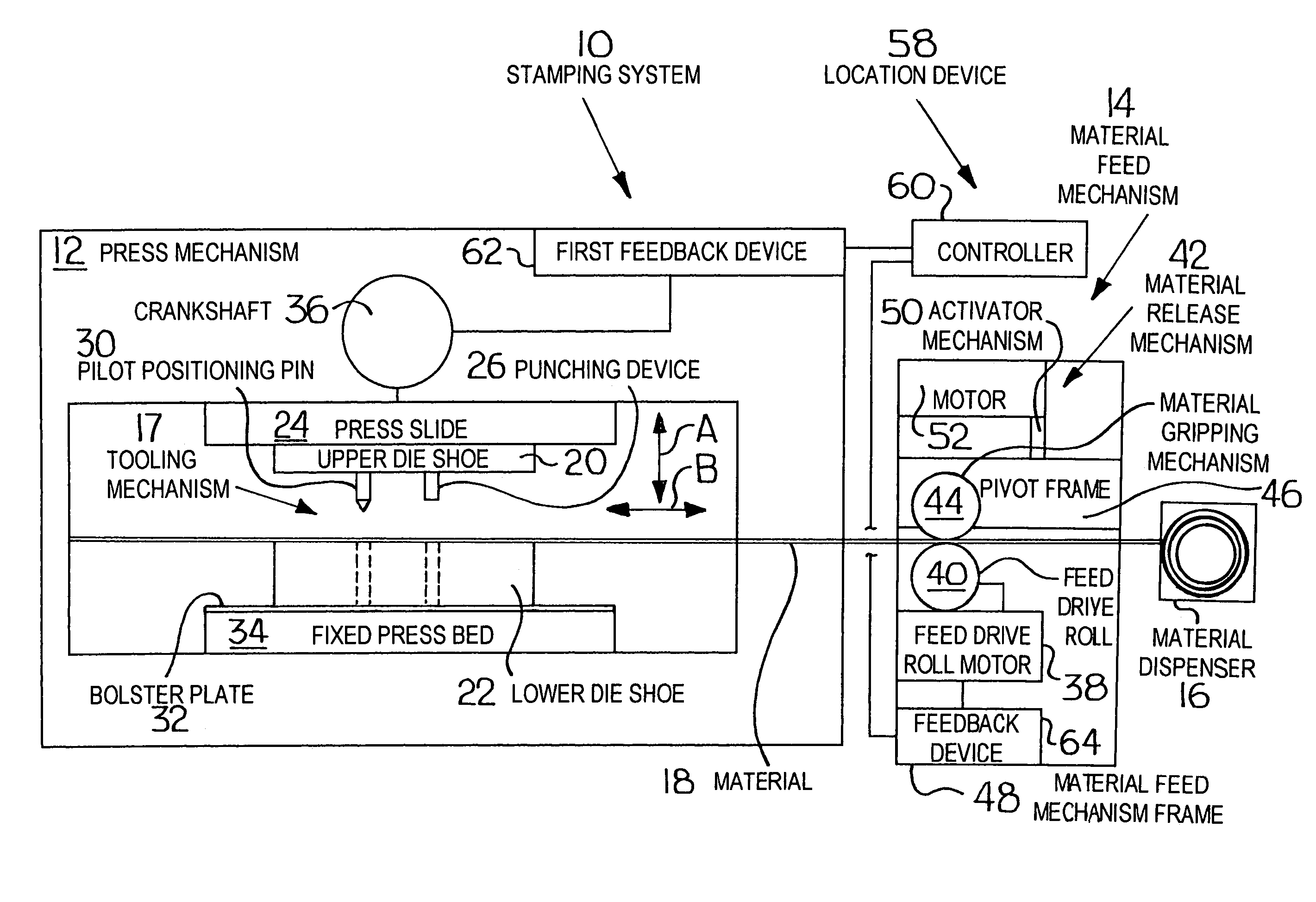
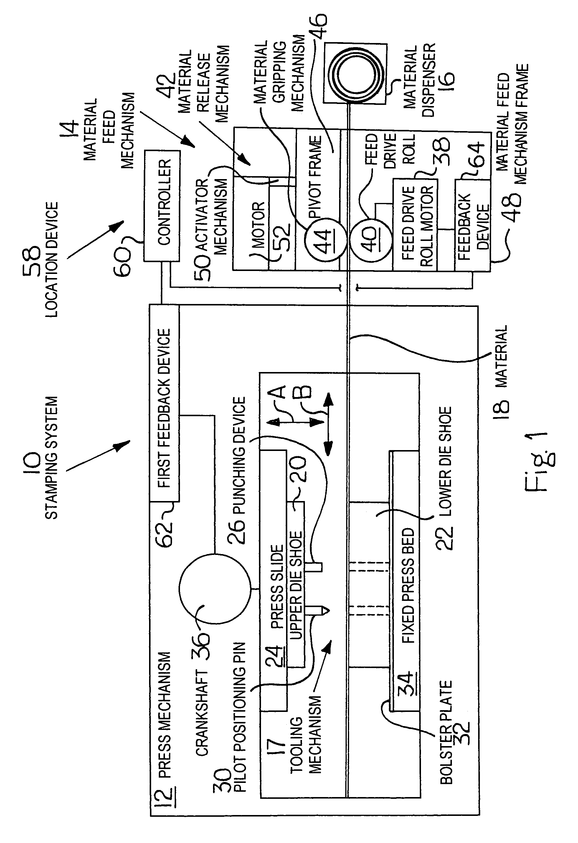
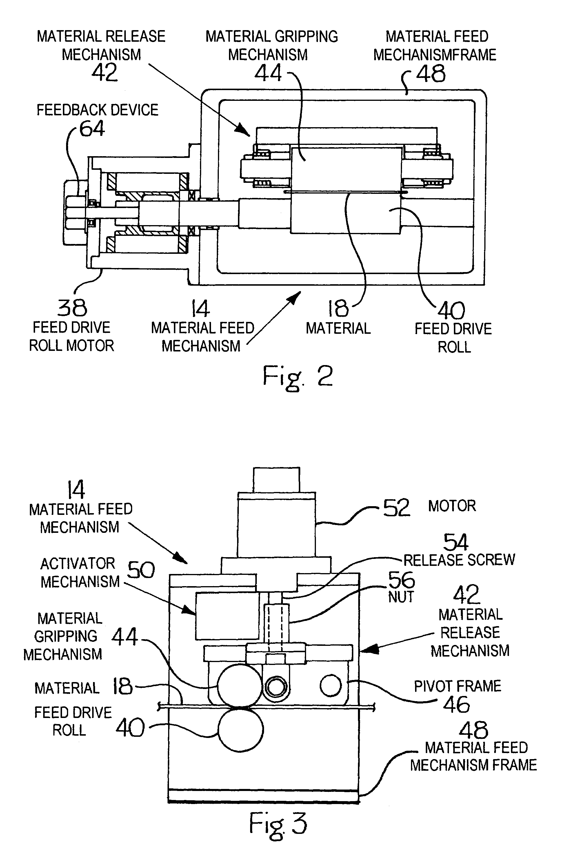
[0020]As illustrated in FIGS. 1-3, the present invention is directed to a stamping system 10, which includes a press mechanism 12, a material feed mechanism 14 and a material dispenser 16. The material feed mechanism 14 is used to feed an elongated strip of material 18 from the material dispenser 16 through the material feed mechanism 14 and into the press mechanism 12. This press mechanism 12 typically includes a tooling mechanism 17 having an upper die shoe 20 and lower die shoe 22. The upper die shoe 20 is mounted to a press slide 24 in the press mechanism 12. The upper die shoe 20 of the tooling mechanism 17 has a punching device 26 and an alignment device 28 mounted on its underside. The punching device 26 is constructed so that it is capable of punching the material 18. In the preferred embodiment, the alignment device 28 is a pilot positioning pin 30. As discussed above, this upper die shoe 20 is mounted to the press slide 24 which, in turn, moves up and down in relation to t...


PUM

PropertyMeasurementUnit
Forceaaaaaaaaaa
Torqueaaaaaaaaaa

Abstract

This invention includes a method of determining the correct timing of a material release mechanism (42) of a material feed mechanism (14) and includes the steps of: cycling a press mechanism (12) through a working portion of a tooling mechanism (17); monitoring the press mechanism (12) position; determining, by a location device (58), the desired timing for the material release mechanism (42) to release contact with material (18); and correlating the desired material release mechanism (42) timing to the press mechanism (12) position. The present invention also is a stamping system (10) for working the material (18). This stamping system (10) includes a press mechanism (12) having a tooling mechanism (17) configured to punch holes (66) in the material (18). The stamping system (10) also includes a material feed mechanism (14) to feed material (18) to the press mechanism (12), and this material feed mechanism (14) includes a material release mechanism (42). Finally, the stamping system (10) includes a location device (58) to monitor the press mechanism (12) position and determine desired material release mechanism (42) timing.

Description

BACKGROUND OF THE INVENTION[0001]1. Field of the Invention[0002]The present invention relates generally to stamping systems having material feed mechanisms and, in particular, to a method and apparatus for determining and setting a material release mechanism timing for a material feed mechanism.[0003]2. Description of the Prior Art[0004]Typically, parts made with an automated stamping press utilize a progressive die set. The progressive die set uses multiple stations, each station typically containing at least one punching or forming punch and a mating die or dies. Continuous strip material, from which the part will be made, is incrementally fed through the die set, progressing from station to station with an automated feeding device. A material feed mechanism intermittently moves the strip material a distance, corresponding to the distance between each die station, while the die set is open. This mechanism then stops the material at each station when the die set closes. Examples of...

Claims


Application Information

Patent Timeline
IPC IPC(8): B65H20/04B23Q15/00B26F1/02B21D43/02
CPCB21D43/021B21D43/09B65H23/1884B41J2/45H01L27/153Y10T83/0481Y10T83/148Y10T83/159
Inventor MARTIN, VAUGHN H.LUKAS, DANIEL G.GENTILE, BRYAN P.CROWELL, MATTHEW C.
Owner VAMCO INT
Why Eureka
Eureka Blog
Learn More