Systems and methods for thermographic inspection of composite structures

a composite structure and thermography technology, applied in the direction of material flaw investigation, optical radiation measurement, instruments, etc., can solve the problems of material deterioration, material may develop cracks or other defects, and defects may not be detected by visual inspection of materials

Inactive Publication Date: 2007-10-30
THE BOEING CO
View PDF14 Cites 47 Cited by
  • Summary
  • Abstract
  • Description
  • Claims
  • Application Information

AI Technical Summary

Problems solved by technology

In particular, the material may deteriorate due to mechanical fatigue and / or environmental exposure so that the various layers in the composite material debond, forming delaminated regions within the material.
In addition, the material may develop cracks and or other defects.
In either case, the defect may not be detected by a visual inspection of the material.
Correspondingly, if the resulting sound has a relatively hollow-sounding report, an internal defect may exist within the material at the location exhibiting the characteristic report.
Although the foregoing method is simple to implement, and is suitable for a field inspection of the composite material, it relies on the subjective interpretation of sounds returned from the material, and may therefore be somewhat unreliable.
Although the subjectivity of the inspector is removed, the method requires a relatively sophisticated apparatus that may not be available for field use.
The foregoing methods generally require the availability of electrical power and therefore may be difficult to use in a field environment.
Other drawbacks may also preclude the use of the foregoing methods in a field environment.
For example, the use of flash lamps to provide a thermal heat input to the composite panel may not be possible in certain field environments.

Method used


Image

  • Systems and methods for thermographic inspection of composite structures
  • Systems and methods for thermographic inspection of composite structures
  • Systems and methods for thermographic inspection of composite structures

Examples


Embodiment Construction

[0014]The present invention relates to systems and methods for the thermographic inspection of composite materials. Many specific details of certain embodiments of the invention are set forth in the following description and in FIGS. 1 through 4 to provide a thorough understanding of such embodiments. One skilled in the art, however, will understand that the present invention may have additional embodiments, or that the present invention may be practiced without one or more of the details described in the following description. In the following discussion, it is understood that the term “composite material” refers to various composite resins, and also to composite resins that are bonded to various metals, such as aluminum, titanium, and other similar materials.

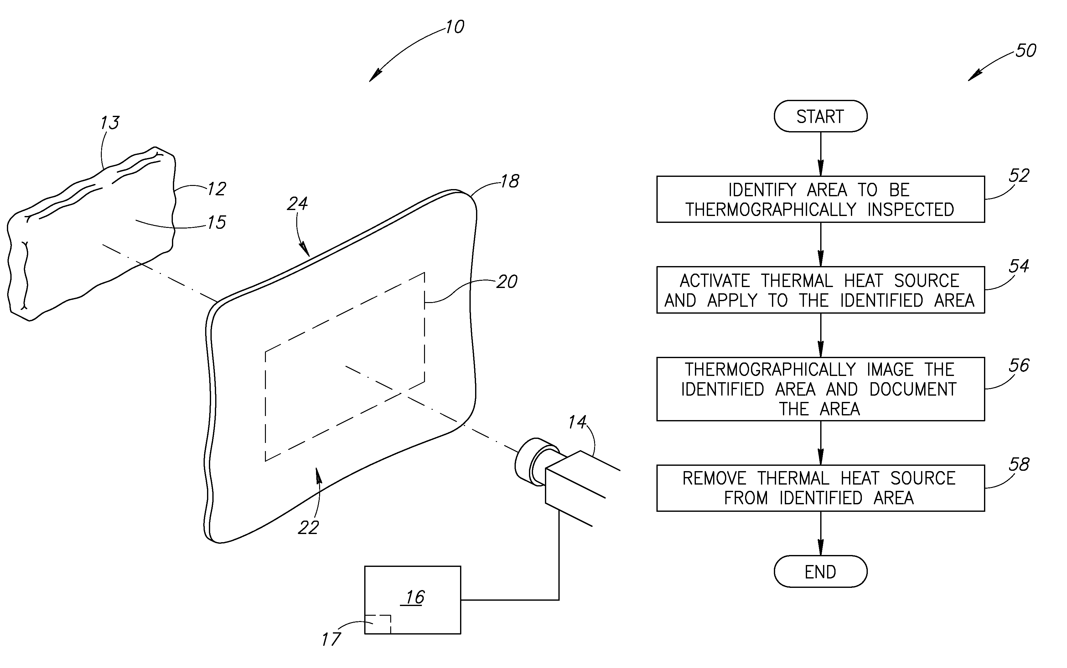
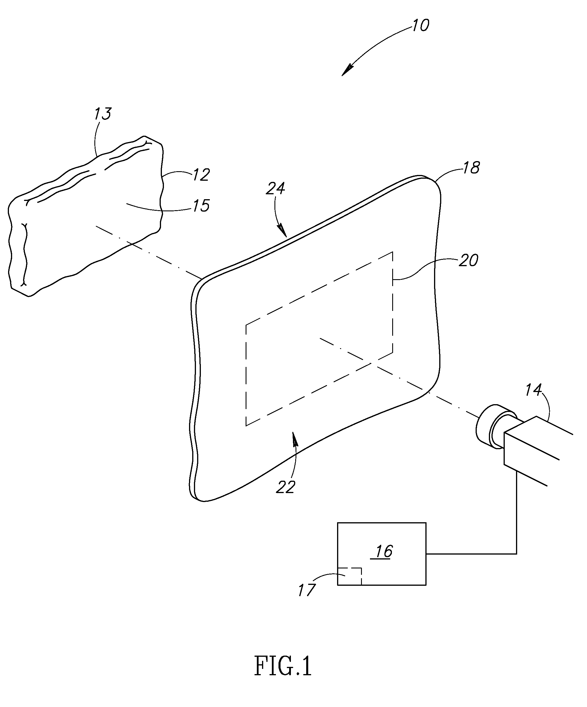
[0015]FIG. 1 is a partial isometric view of a system 10 for thermographically inspecting a composite material, according to an embodiment of the invention. The system 10 includes a thermal heat source 12 that is operable to pr...


PUM

PropertyMeasurementUnit
temperatureaaaaaaaaaa
thermal fieldaaaaaaaaaa

Abstract

Systems and methods for thermographically inspecting a composite material or honeycombed type structures are disclosed. In one embodiment, a system includes a thermal heat source configured to be either removably coupled to or positioned proximate to the composite material to generate a localized thermal field in a selected area of the composite material. A thermal imaging device generates a visible image of the generated thermal field.

Description

FIELD OF THE INVENTION[0001]This invention relates generally to material inspection systems and methods and, more specifically, to systems and methods for inspecting composite materials using thermography.BACKGROUND OF THE INVENTION[0002]Composite materials are increasingly used as substitutes for conventional materials such as aluminum and steel alloys in various structural components due to the generally high strength-to-weight ratio inherent in composite materials. Composite materials may generally be comprised of a network of reinforcing fibers that are generally applied in layers, and a polymeric resin that substantially wets the reinforcing fibers to form an intimate contact between the resin and the reinforcing fibers.[0003]Composite materials exhibit modes of failure that are distinct from failure modes present in conventional materials. In particular, the material may deteriorate due to mechanical fatigue and / or environmental exposure so that the various layers in the compo...

Claims


Application Information

Patent Timeline
Patent Type & Authority Patents(United States)
IPC IPC(8): G01N25/72
CPCG01N25/72G01J2005/0077
Inventor SAFAI, MORTEZAGEORGESON, GARY E.SPALDING, JR., JOHN F.THOMPSON, JEFFREY G.
Owner THE BOEING CO
Why Eureka
Try Eureka