
Cascade system for network units

a network unit and cascade technology, applied in data switching networks, frequency-division multiplexes, instruments, etc., can solve the problems of increasing hardware processing overhead, complex forwarding rules, and imposing considerable complexity in the design and organisation of cascades

Inactive Publication Date: 2007-10-30
HEWLETT-PACKARD ENTERPRISE DEV LP
View PDF28 Cites 22 Cited by
  • Summary
  • Abstract
  • Description
  • Claims
  • Application Information

AI Technical Summary

Benefits of technology

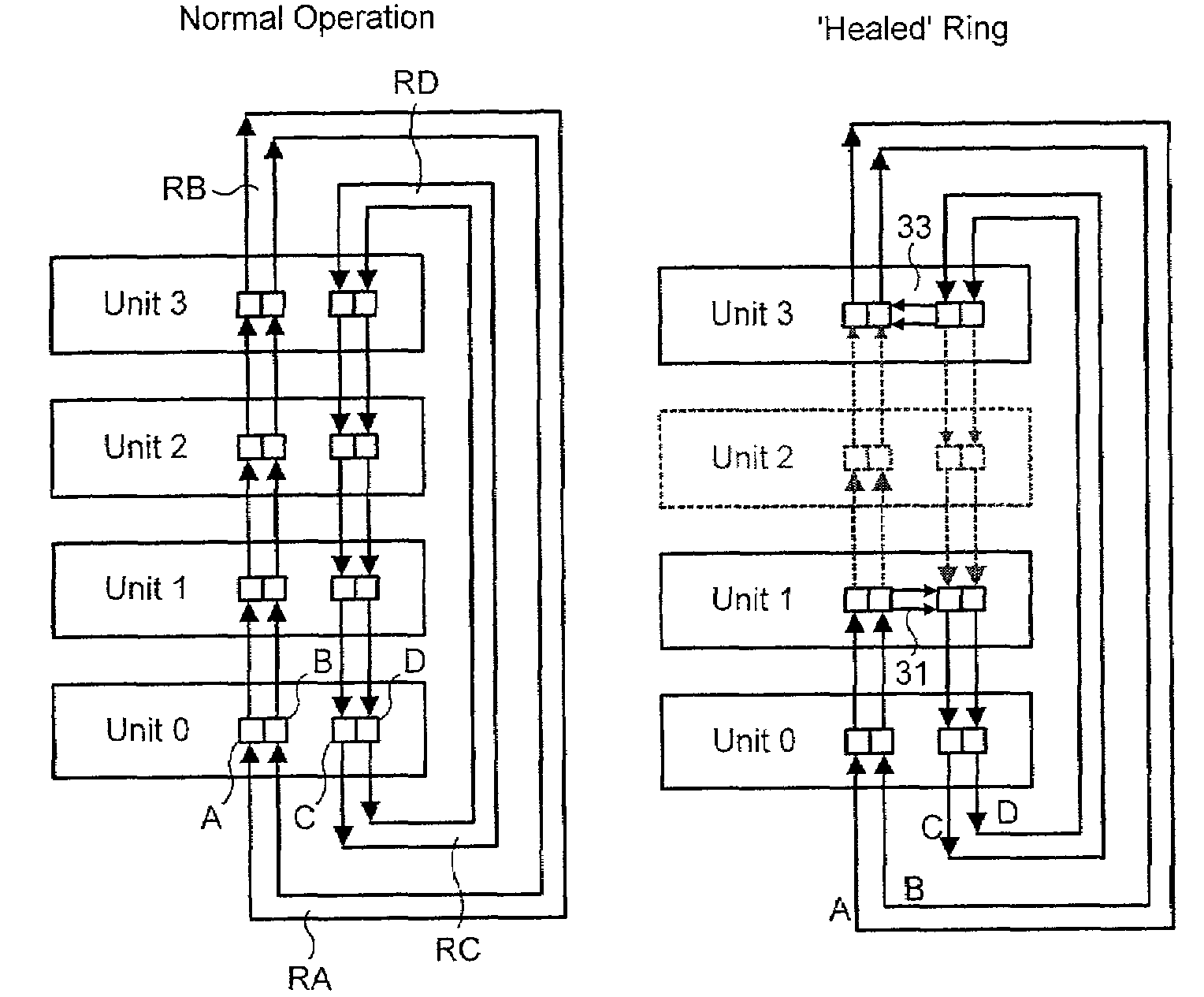
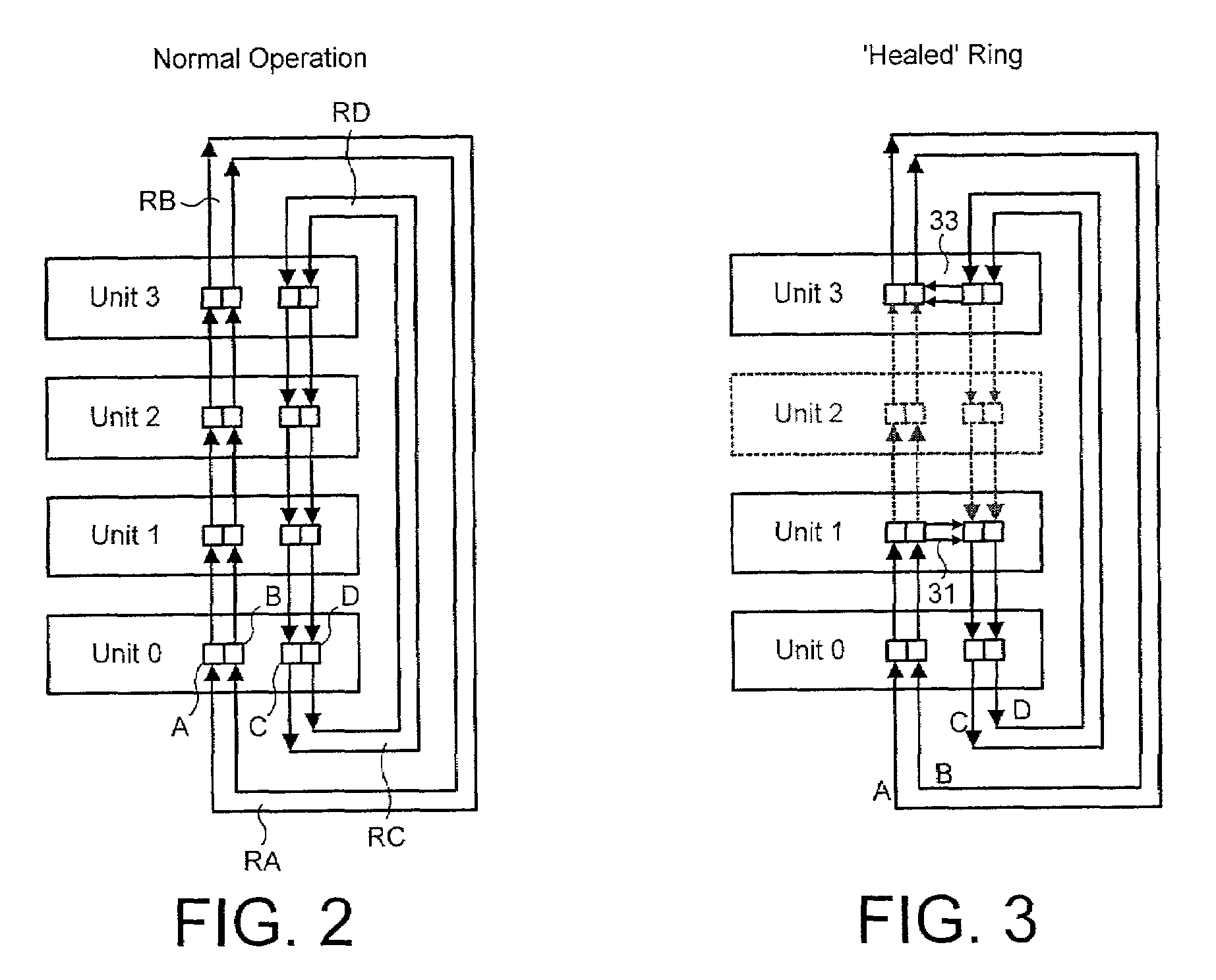
The present invention provides a self-healing hot-swappable cascade connection that allows for hot insertion or hot-swap of units. The invention includes physical and logical organization of the cascade connection, as well as a preferred signal format for use on the cascade. The invention also provides mechanisms for healing the cascade in the event of failure or removal of a unit or cable, such as bypass operations and the use of headers and identifiers. The invention also includes a stack-wide port identification system and a header segment to identify the source unit and the port within a unit. The invention can be used in conjunction with an improved control path and without requiring special multiplexer connectors.

Problems solved by technology

The design and organisation of a cascade are attended by some considerable complexity.
An added difficulty arises when it is desired to form a cascade connection of units such that the connection can accommodate the addition of units into the cascade or the removal of units from the cascade or even the failure of one or more units in the cascade or failure or removal of links (such as cables) between units without requiring manual adaptation or reconfiguration and which allows the augmented or diminished or partially defective cascade to continue operation after only a momentary delay.
That earlier proposal requires in its described form complex forwarding rules which are not easy to accommodate with other forwarding rules that the units may need to observe.
However, these circuits and the associated multiplexing impose a considerable hardware processing overhead which increases (owing to the need for active clock and data recovery) with higher bit rates.

Method used


Image

  • Cascade system for network units
  • Cascade system for network units
  • Cascade system for network units

Examples


Embodiment Construction

(a) General Description of a Switch

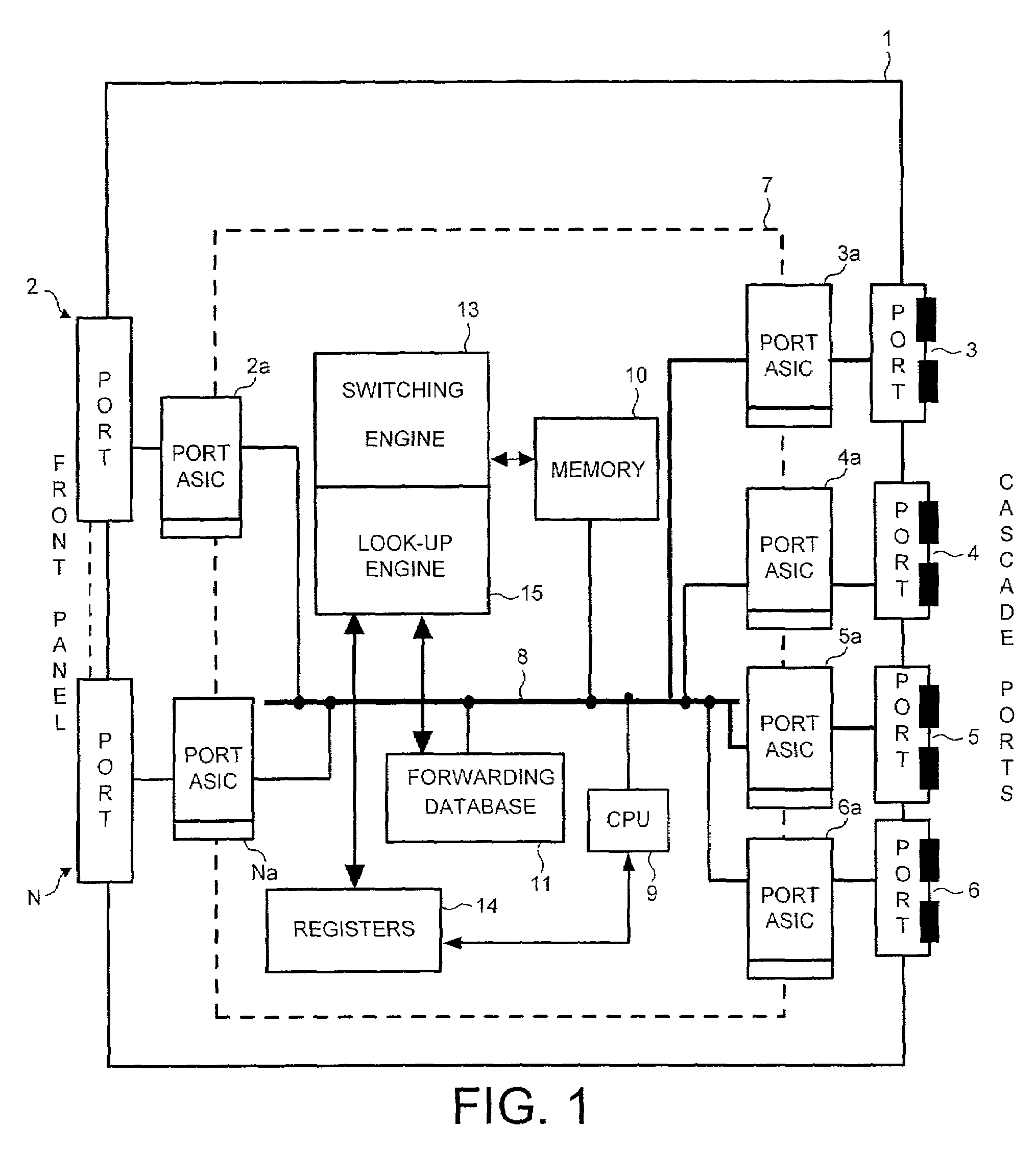
[0043]The reader is presumed to be generally familiar with the design construction and operation of network switches and routers intended for the handling and processing of address data packets, particularly according to Ethernet formats and protocols and procedures in accordance, for example, with IEEE Standard 802.3 dated December 1998. However, for the sake of completeness, a brief and deliberately simplified review of a network switch is given hereinafter for the sake of convenience. A more detailed description of the features of the switch relevant to the present invention will be given with reference to FIG. 18.

[0044]The switch 1 shown in FIG. 1 comprises a multiplicity of ordinary or ‘front panel’ ports represented in the Figure by ports 2 to N. Very typically there would be twelve or perhaps twenty-four of these front panel ports, which are selectively connected to other devices such as hubs, switches, user terminals and suchlike typical of...


PUM


Abstract

Network units such as switches for use in a cascaded stack are organised to provide a cascade connection in the form of a dual unidirectional connection so that, in its ordinary configuration, there is at least one and preferably more than one unidirectional ring for each direction around the cascade, each ring including a respective port on each unit. For each ring, each port on a unit is connected by a respective link to a corresponding port on the preceding unit and the following unit. The units provide a self-healing operation in the event of various kinds of operational failure. The self-healing operation includes loop-back of packets in units adjacent the failure and bypass of a packet switching process for other units. The units include control logic for passing control frames containing status information relating to the units and links between them and for co-operation with a CPU to control a switching engine to perform the self-healing operation in accordance with that status information. The units forward on the cascade packets with headers that identify a destination port and the unit on which that port is located and also indicate which units have and have not been traversed by a packet.

Description

CROSS-REFERENCE TO RELATED APPLICATION[0001]Donoghue et al, entitled ‘Cascade Control System for Network Units’ filed on the same day as the present application and commonly assigned herewith.FIELD OF THE INVENTION[0002]This invention relates to packet-switched communication networks. More particularly the invention relates to networks compatible with ‘Ethernet’ transmission formats and protocols. The invention specifically concerns what is known as the ‘cascading’ of switches or other units in or for such a network. Various aspects of the invention concern the logical management, control and signal formats preferably incorporated in a cascade.BACKGROUND TO THE INVENTION[0003]The physical elements in a packet-based data communication system commonly include multi-port units such as switches and routers. Such units are commonly and conveniently manufactured with a fixed plurality of ports by means of which the units can be connected by way of appropriate transmission links (such as c...

Claims


Application Information

Patent Timeline
Patent Type & Authority Patents(United States)
IPC IPC(8): H04L12/50H04L12/433
CPCH04L12/433
Inventor DONOGHUE, BRYAN JTRAN, QUANG TO'NEILL, EUGENELAW, DAVID JMORAN, PAUL JO'MALLEY, EDELENOLAN, JEROMECHOI, KAMGOODFELLOW, MAURICE A
Owner HEWLETT-PACKARD ENTERPRISE DEV LP
Learn More